III.2.7�������� Data Escrow and Backup (RFP Section D15.2.7)
JVTeam will back up the databases in our data centers in Sterling, VA and Chicago, IL, and will regularly place escrow copies of the backups in secure off-site locations. These procedures are essential elements of our realistic plans for continuity of operations in the event of system failures and natural or man-made disasters.
The goal of any data backup and recovery procedure is full recovery from failures without any loss of data.� Data backup strategies handle system hardware failures (e.g. loss of a processor or one or more disk drives) by reinstalling the data from daily backups, supplemented by the information on the �before� and �after� image-journal backup files that the database creates.
The conventional strategy for guarding against loss of the entire facility because of fire, flood, or other natural or man-made disaster is to provide off-site escrow of the registry data in a secure storage facility.� Even when successful, this recovery strategy does not prevent the loss of a certain volume of transactions between the time the data was backed up and the occurrence of the disaster. Users are subject to denial of service during the time required to recover the data-center database and/or reestablish operations at an alternate disaster-recovery site.� Relocating the data center normally requires at least 24 hours, and the escrowing of backups often is done only weekly, meaning that a disaster could result in substantial loss of both services and data.
JVTeam�s backup solution goes a step further. We propose two co-active SRS data centers, each capable of handling the entire workload should a major system failure or natural or man-made disaster occur at the other. The transactions from each data center are replicated in real time to the other over a redundant high-speed Virtual Private Network (VPN) telecommunications links. Each SRS data center also conducts independent backups, as described in the following paragraph. Since the two SRS data centers are co-active, our backup strategy maintains continuity of operations and enables full recovery of all transactions, even in the event of multiple hardware failures.�
III.2.7.1����� Frequency and Procedures for Backup of Data�
Each co-active data center independently implements a zero-downtime/zero-impact incremental data backup each day, and a full data backup weekly. We place escrow copies of the backup tapes in a secure off-site storage facility operated by a third party whose business is data escrow. We copy static data (e.g., the operating systems, BIND software, applications software) to CD-ROMs for quick reload, should that become necessary.� We back up to DLT tape any dynamically changing files (e.g., log files vital to system maintenance and operation, database files, database-journal files, software configurations). Weekly, we perform full-system backups to DLT tape of all databases identified in Section III.2.3 (SRS DB, Whois, Billing).
Each data center uses on-line zero-downtime/zero-impact,
backup procedures that include the following 4 steps:
1.
The
database is put into backup mode to guarantee a consistent version of the data
on the snapshot copy that is written to a RAID disk array for subsequent
(slower-speed) copying to tape. While the database is in backup mode,
the XRP, Whois, and Billing applications continue to function and to access the
data.� The database normally is in
backup mode for only about 5 to 10 minutes.
2.
The
backup software writes the data to the RAID disk array.
3. The backup software, which is located on a backup server independent from the application servers, creates the backup DLT Tape copy from the snap shot copy on the RAID disk array.
4. When the backup is finished, the DLT Tapes are transported to the secure escrow facility.
III.2.7.2����� Backup Hardware and
Software Systems
Exhibit III.2-19 depicts the SRS data centers� backup and recovery hardware and software. Each data center�s system includes two backup servers with DLT robotic tape libraries.� The data backup system uses the DLT IV data cartridge and the DLT 5 data format. To achieve zero-downtime/zero-impact backup, we use a RAID disk array and a high-speed-fibre, channel-bridge interconnect to the robotic tape libraries. The backup server copies not only the database-server�s backup files to the disk array, as discussed in the 4-step process already described, but also the backup files of the cluster servers. During the few minutes this process requires, applications still have access to the cluster servers and database server.� Then the backup server copies the files to the DLT Robotic tape device. This approach ensures that we can meet our Service Level Agreements (SLAs).
Due to the criticality of the database, the JVTeam proposes a fully redundant, fault-tolerant database management system. We will configure the database system as two independent database servers � primary and backup � with synchronous replication using two-way commits to maintain database synchronization. If one database server fails, the database system is sized so that the second server can process the entire load without degradation while the primary server is restored to service.
We will transport both daily incremental backups of dynamically changing data and the weekly full backup to a secure escrow agent to be selected with the concurrence of ICANN.
III.2.7.3����� Procedures for Retrieval of Data and Rebuild of the Database.
We maintain copies of the DLT tapes holding incremental data backups in a three tape rotation:
� One DLT backup tape is in transit to the secure escrow facility.
� A second DLT tape is in storage in the secure escrow facility
� The third DLT tape is in the data center for reuse.
The full backup tapes are maintained in a 2-tape rotation, with one tape at the secure escrow facility and one at the data center for reuse. A copy of the static-data CD ROMs for the operating systems and applications are also maintained at the escrow facility.
Should the primary database server experience a catastrophic crash that necessitates a lengthy recovery process, data-center operations continue seamlessly on the backup database server that replicates all the data in the primary.� After the failed database server is repaired, we recover its data using the full backup tape and incremental backup tape that is retrieved from the escrow facility. We first restore the full backup files; then, the incremental files. We then synchronize the recovered database to the primary database. This procedure recovers the database to the last complete transaction processed by the primary database.
This backup procedure enables JVTeam to meet the service level agreements required for continuous availability and near-zero unplanned downtime, thereby improving the stability of the Internet, enhancing public confidence, and improving customer satisfaction.
III.2.8�������� Publicly Accessible Look Up/Whois Service (RFP Section D15.2.8)
JVTeam proposes a Whois service that will eliminate problems associated with the current multiple Whois systems.� The most serious of these problems is a genuine threat to the stability of the Internet: the possibility that relying on Whois information that can be at least 12 hours out of date could result in an erroneous change relating to the domain name of a large Internet site that performs millions of dollars worth of e-commerce transactions daily.
Whois is a database of information about Internet domain names.� JVTeam�s proposed registry will maintain a state-of-the-art, real-time Whois service that will make this information available on the common Whois port (Port 43).� Our registry will store all information relating to Whois data entities, including contact and authentication data.�
The Whois service is intended as a directory service for registrants, as well as for any other individuals and businesses that want to query details of domain names or related data stored in the registry.� Our Whois data will be available in both conventional and machine-readable format, facilitating automation.� Further, the level of information displayed will be configurable.
Registrars will provide the front-end web interface to the Whois directory.� Because this interface will be a simple wrapper around the registry�s Whois service, the registrars will have complete control over the service�s look and feel and branding.� With this control, registrars will be able to comply with the privacy restrictions enacted by the countries where they operate.
Problems with Current TLD Whois Service
The current .com/.net/.org Whois service has caused many problems for both registrars and registrants.� The system has confused registrants, and its inherent problems have increased costs (and risk) to registrars, who had to provide manual processing or recovery from failures in automated processes.� Inherent system problems include the following:
� Different protocols used (i.e., not all registrars use Whois on Port 43)
� Different fields exposed
� Different formatting of data
� Timing inconsistencies (regarding adding, deleting, transfer of registrar, etc)
� Not real time (Whois is updated only every 12 hours)
� No standard machine-readable format
As a result of these system problems, records in a registrar�s Whois can contradict those in the registry�s Whois, or records in two registrars� Whois services can contradict each other.� The most serious problem with the current system and an issue of serious concern relating to the stability of the Internet is that a gaining registrar uses the Whois service to determine if a Transfer of Registrar request is authentic.� If a mistake is made in the transfer of registrar, an incorrect owner could redelegate a domain name (or change ownership), potentially bringing down a large Internet site performing millions of dollars of e-commerce transactions per day.
Benefits of Proposed Solution
The system problems cited in the preceding paragraph could theoretically be solved with stronger enforcement of technical standards, such as protocols, fields, and data formatting.� JVTeam�s proposed solution centralizing the Whois data and providing access via registrars is more pragmatic and will solve all current problems.� Our solution would provide:
� Central location for all authoritative TLD data
� Standard protocol accessible over port 43
� Consistent format (fields, formatting, etc) for all registrars
� Machine-readable format (promotes automation)
� Elimination of �timing� problems when modifying entities
� Real-time update
� Extensible field capability.
III.2.8.1����� Whois Service Functional Description
The Whois service will accommodate queries regarding the data entities listed in the following table.
|
Entities |
Fields |
|
Domain names |
Attributes (Status) Associated nameservers Associated registrar Associated registrant data |
|
Nameserver |
Attributes (Status) Associated IP addresses Associated registrar Associated registrant data |
|
IP Address |
Attributes (Status) Associated nameserver Associated registrar Associated registrant data |
|
Registrar List |
Registrar name |
|
Registrars |
Registrar name Registrar contact details Registrar URL (Home page) Registrar Whois URL (Web Port 80) Registrar Whois URL (Port 43, if applicable) Attributes (Status) |
Machine-Readable Format
JVTeam�s standardized Whois format will facilitate automated parsing of Whois information
Because the viewable data could be modified over time (e.g., new fields could be added), a more robust and formalized encoding mechanism is needed to provide the non-Registrar community reliable automated access to Whois data.
For example, an organization tracking trademark infringement might want to acquire the Whois data, automatically parse it, and store it in a tracking system.� To accommodate such organizations, which will not have access to the XRP protocol, the Whois information must be presented in a formal, extensible way that is compatible with automated processing.� To accomplish this, we will present the Whois data in an open, standard, XML-based, machine-readable format that we designate as the XWP (eXtensible Whois Protocol).� The information accessible via the XWP is inherently tied to the XRP (eXtensible Registry Protocol) data requirements, and thus, will be part of the same standardization process.� Just as we will do with the XRP, JVTeam commits to submitting the XWP to an industry standards body for adoption and future modification according to that body�s normal procedures.
Extensible-Field Capability
In the spirit of providing advanced services to the registrar community, JVTeam will introduce the ability for registrars to use XRP to add customized fields to a record in the registry database.� These fields will appear in an �additional information� section of the Whois data.� The maximum number of custom fields allowed per record is yet to be determined.
The extensible-field capability will eliminate the need for registrars to store additional information in their own local database, then combine it with the registry Whois information when they present it to end users.� The proposed capability will also ensure that end users will view the same information no matter which registrar they use to retrieve Whois data.
All custom fields would appear in a special additional information section at the end of the uniform Whois data.� In human-readable form, the customized fields could appear as follows:
Additional Information:
���
<name>: <value>
���
<name>: <value>
��� �
In XWP format, the customized fields could appear as
follows:
<additional>
���
<custom name=�xxxxxx� value=�yyyyyy�/>
���
<custom name=�xxxxxx� value=�yyyyyy�/>
</additional>
JVTeam intends to provide extensible-field functionality during any Sunrise period to support publishing of trademark (and associated) information.
Bulk-Access Program
Much of the load placed on the current .com/.net/.org Whois service is caused by automated programs mining for data.� Because Whois data is publicly accessible, this will always occur; however, JVTeam proposes to provide a data mart. that limits the recipient�s conditions of use.
The proposed data mart bulk-access program would:
� Reduce the load that data mining currently imposes on the core Whois service
� Contractually limit subscribers in the ways they can use the data
� Provide a source of revenue to fund advanced service levels
� Reduce the incentive to download entire database without legitimate purpose
� Provide the entire database in a format that facilitates such data mining as conducting trademark searches, compiling industry statistics, and providing directory services.
The registry will make the Whois data available to registrars, who will conduct the actual bulk-access program.� Data will be exposed only within the privacy restrictions described in the following subsection.
Privacy Restrictions
A number of
countries have enacted privacy laws (e.g., the European Union Privacy
Directive) that restrict the
information that can be presented in the Whois service.� Under the terms of its licensing agreement,
JVTeam will bind registrars to comply with all applicable privacy laws while
providing Whois services.
Each registrant
account will have a privacy attribute that can be set to one of the following
levels:
�
Unrestricted�Complete registrant details displayed
�
Restricted�Registrant name and address displayed
�
Private�No Registrant details displayed
Registrants in
countries that have enacted privacy laws can select the privacy level permitted
under law.� No matter which level they
select, such details as the delegated nameservers and associated registrar will
still be visible.
Private information will be released only under court order or the direction of some other authority that has legal jurisdiction to demand such release.
Restricting
private data will not create problems for registrars� �Transfers of Change of
Ownership� transactions because these operations will be conducted using the
centralized authentication mechanism.
III.2.8.2 ���� Whois System Architecture
JVTeam will deliver a Whois service that incorporates semi-real-time update, scalable infrastructure, and multiple layers of redundancy.�� We will initially deploy the Whois servers at the two co-active SRS data centers shown previously in Exhibit III.2-1.� The software architecture will enable us to deploy Whois infrastructure to any number of additional JVTeam data centers.� As the registry grows, we will deploy additional Whois infrastructure as appropriate to increase geographic dispersion, enhance the level of service in particularly geographic regions, and reduce the load on the SRS data centers.� We are willing to negotiate with ICANN about adding and siting additional Whois services.
Exhibit III.2-20 illustrates the Whois architecture.� At each Whois site, incoming queries are distributed by a load balancer to a cluster of Whois servers, which are, in turn, connected to a backend database cluster.� This configuration will provide both redundancy and scalability through the addition of servers to either cluster.
Each Whois server will cache common requests in memory and query the back-end database cluster only on a cache miss.� We can configure the duration that Whois information is cached before being deleted (e.g., 10 minutes); after deletion, the server must query the database for the information.� Each Whois server will be configured with at least 2 GB of high-speed memory, sufficient to hold at least one million of the most commonly queried Whois records.�
Exhibit III.2-21 depicts the update of the Whois databases.� As the SRS database is updated, the system will also update the Whois distribution database server in real time.� This database will be replicated to the Whois databases within defined service levels (e.g., 10 minutes).� Replication between data centers always occurs over a VPN or a dedicated link, and the registry will digitally sign update packages.�
The proposed Whois service offers the following benefits:
� Service can be scaled by adding servers to each Whois cluster
� Databases can be scaled by adding machines to each database cluster
� Service can be scaled by deploying Whois infrastructure to additional data centers
� Inherent redundancy ensures high availability
� Update process ensures near-real-time availability of the latest information
�
Caching of common queries provides superb response
time.
III.2.8.3 ���� Network Speed and Proposed Service Levels
The large volume of Whois queries places a significant network-connectivity burden on the registry.� Based on the assumption that each Whois query will generate approximately 10 Kbits of network traffic, we will use the following engineering guidelines for provisioning bandwidth:
� Initially, we will provide 25 Mbits per data center.� The total of 50 Mbits will support approximately 5,000 queries per second (approximately 430 million requests per day).
� As the volume of registrations grows, we will extend the service at a rate of 10 Mbits per one million domain-name registration records under our management.� For example: when the registry manages 20 million domain names, we will dedicate 200 Mbits of Whois bandwidth, which will support nearly two billion Whois queries per day.
These guidelines will be compared with actual usage data and adjusted accordingly.
We will engineer the Whois service to provide the following average service levels, and are willing to negotiate service levels:
� 400 million queries per day (90% cache hits, 10% cache misses, which must be forwarded to database file).� We will increase this query-service demand based on the total number of domain name registrations managed by the registry, as previously discussed.
� 200-millisecond latency for cache hits (after the request reaches the data center).
� 500-millisecond latency for cache misses (after the request reaches data center).
We will configure the Whois service to limit connections based on the following criteria:
� 1000 queries per minute from any single IP address
� 20,000 queries per minute for requests originating from designated registrar subnets
� An �acceptable use� policy that we will negotiate with ICANN and the registrar community.
We will scale the exact number of Whois and database servers deployed in each cluster and at each data center to maintain the specified service levels.
III.2.9�������� System Security (RFP Section D15.2.9)
JVTeam is currently operating successful data centers for various telecommunications and domain-name� registry services.� This experience has familiarized us with security risks, as well as with the most current and effective means of thwarting such risks.� ICANN can be assured that our comprehensive security provisions will protect the TLD infrastructure, operations, and data.
Shared Registration System (SRS) and nameserver data centers are subject to a wide range of security threats, including hacking, break-ins, data tampering, denial of service, and physical attacks against the facility.� The recent denial-of-service attacks against important government and dot-com sites point to the technical capabilities of some hackers and the lengths to which they will go to attack the Internet community.� Further, because the Registry will contain proprietary data from competing registrars, security procedures must incorporate user-authentication procedures that ensure that each registrar�s files are available only to its own personnel.
Failure to address these
security threats creates the risks of unscheduled down time and the disruption
or denial of services.
This section describes
system-security features that we will implement in our networks, servers, and
applications for the SRS data centers and nameserver data centers.
III.2.9.1����� System Security
JVTeam offers ICANN comprehensive system security for our networks, servers, applications, and customer support services. Our security architecture is a policy-based, multi-tiered structure based on industry standards and on evolving new IEFT standards for registry-to-registrar security and secure DNS. Our solution integrates the following security features to provide assurance that multiple security threats or attacks will be unsuccessful:
� Perimeter protection for Whois and DNS applications
� C-2-level controlled access at the server operating systems
� Applications-level security features for XRP, Billing & Collection, and customer-service applications
� Connection security
� Data security
� Intrusion detection
� User identification and authentication
� Continuity of operations
� Physical security.�
Exhibit III.2-22 depicts our implementation of these security features to prevent system break-ins, data tampering, and denial-of-service attacks.
III.2.9.1.1��� Shared Registration System Data Center Security
Network Security
Edge routers, firewalls, and load balancers provide perimeter protection for the data-center network and applications systems, guarding against unauthorized access from the Internet.
� Edge Router�The first security layer is the edge routers, which employ IP-packet filtering.�
� Firewall�The second layer of perimeter security is a firewall that provides policy-based IP filtering to protect against system hacks, break-ins, and denial of service attacks. The firewall also includes network-based intrusion detection to protect against Internet hackers.
� Load Balancer�The third layer of protection is provided by load balancers within each data center.� Load balancing protects our application servers from common denial-of-service attacks; e.g., SYN floods, ping floods, and �smurfs� attacks. Security policies can be based on any combination of source address, destination address, and protocol type or content.
� Virtual Private Network (VPN)�The registry network will use VPN technology to perform database updates at the nameservers, network-based backup/restore, remote system/network management, and system administration.� Our goal is to operate the nameserver data centers sites in a �lights out� (unmanned) mode. VPN technology achieves secure data transfer through encrypted data-communications links.
Server Security
The SRS operating systems provide C-2-level access protection through a user login procedure and through file-level access-control lists. These access-control mechanisms perform the following functions:
� User-account security, which establishes the access capabilities of a specific authenticated user. After authenticating a user, each application�s security-data tables control access to information.� Access is based not only on user-id, but also on the type of application being used; e.g., XRP, Billing and Collection, etc. The application server uses user-id to provide precise control of access privileges to � and uses of (read, write, execute) � all system resources: screens, menus, transactions, data fields, database tables, files, records, print facilities, tape facilities, software tools, and software executables.
� Group-level security, which establishes the access capabilities of all users within a specific group.� All users belong to one or more access-control groups.� Access control is identical to that for individual users.��
� System Administration-level security, which restricts access to system administration tools, including the ability to change resource-access privileges. SRS system-administration staff use dedicated links on an internal LAN/WAN to access administrative functions that are off-limits to others.� There is no external access to this LAN.� All sessions require user identification by user name and password; access control lists determine what resources a user or user group is allowed to access and use.
The SRS operating systems will perform security-relevant logging functions, including:
�
User Login�Whenever a user login is attempted,
whether successful or not, the event is logged.� The logged information includes the user-id, time, and device
requested.
�
User Accounting��User Accounting� logs every
process executed by every user.� The
output includes date and time, user-id, point of entry, process, resources
accessed, and result of the operations.��
This log may be selectively viewed for actions performed by a specific
user or users.
�
System Logging�This inherent, configurable
logging capability permits monitoring the kernel, user processes, mail system,
authorization system, etc.� In addition,
the operating system detects when file-access privileges have been changed, and
also audits the use of telnet, finger, rsh, exec, talk, and similar operations.
The following provisions apply to passwords:
� Passwords must be at least six alphanumeric characters in length.� At least one character must be alphabetic; at least one must be a numeric or punctuation character.
� If a user forgets his/her password, the system administrator verifies the user�s identity, and then provides the user with a temporary password that enables him/her to log on only to the site where users create their own new passwords.
� Passwords are valid only for a pre-established duration (typically 90 days, but re-configurable).� Prior to password expiration, the system instructs the user to create a new password.�
� When a user changes his/her password, the system first re-authenticates the existing password, and then requires the user to verify the new password before accepting the change. The system will not accept, as a user�s new password, either of that user�s two most recent passwords.
� Passwords are encrypted and stored in an inaccessible system file.�
Application Security
Each SRS application will have its own set of security processes and technical controls. The SRS applications that interface with the registrars (e.g., the XRP and the Secure Web Customer Service portal) employ the SSL (secure sockets layer) protocol element that uses public-key exchange and RC4 encryption.� Public services (e.g., Whois, DNS queries, and the public Internet Web portal) rely on the previously discussed network perimeter-security devices � edge routers, firewalls, and load balancers � to protect the internal LAN and applications servers.
� XRP Applications Security�JVTeam�s XRP server authenticates against a series of security controls before granting service, as follows:
1. The registrar�s host initiates a SSL session with the XRP server
2. The XRP server receives the registrar�s private key with the incoming message and authenticates it against the registrar�s public key, which is stored in the registry�s XRP server.�
3. After the XRP server verifies the key exchange, it completes the SSL initialization to establish a secure, encrypted channel between itself and the registrar�s host computer.� This secure, encrypted channel ensures the integrity of the registrar�s session with registry applications.
4. In combination with completing the SSL connection, the XRP server authenticates an X.509 digital certificate to verify the registrar�s identity. Digital certificates are maintained in the SRS authentication server database.�
5. The registrar logs on to the XRP server using a userid and password that determines access privileges.� We will provide each registrar with multiple userids and password pairs, so that each can establish its own group of authorized users.
� Whois Application Security�Although any Internet user has read-only access to the Whois server, JVTeam�s perimeter-security mechanisms�edge routers, firewalls, and load-balancers�will protect it against denial-of-service attacks. A designated registry administrator performs common database-administration tasks on the Whois database, including monitoring its performance.
� Nameserver Security�Just as they have with the Whois servers, all Internet users have read-only access to the nameservers.� Similarly, the edge router, firewall, and load-balancers protect the nameservers as they do the Whois servers.
� Secure-Web Customer-Service Portal�The secure-web customer-service portal uses the same security mechanisms employed by the XRP server; namely, SSL session encryption, digital certificates, and userid and password between the SRS secure web server and the registrars� Web browsers. In addition, e-mail messages are encrypted with a Pretty Good Privacy (PGP) public-key-infrastructure implementation. Digital certificates are maintained in the authentication server.
The following table summarizes the benefits of each security mechanism that we employ at the data centers to prevent system hacking , break-ins, and denial-of-service attacks..
|
Security System |
Features and Benefits |
|
Server
Operating-System Security |
|
|
User ID and password;
file-level access-control lists |
Ensures that the user can
access authorized functions, but no others, and can perform only authorized
operations within these functions.�
For example, the registrar of a registered domain name is authorized
to query it and then renew or cancel it or change its nameservers, but cannot
query domain names held by other registrars. |
|
Database
Security |
|
|
User ID and password;
user profiles |
�
Limits database access to pre-authorized users. �
Retains the last two passwords and disallows their usage. �
Rejects simultaneous sessions by an individual user. �
Stores user profiles. �
Limits access rights to database objects and functions to
a specified user or user group. �
Rejects unauthorized access attempts.� Automatically revokes identification codes
after a pre-established number of unsuccessful attempts. �
Provides a non-technical user interface to facilitate the
on-line administration of user privileges. |
|
Application
Security |
|
|
SSL v3.0 protocol |
HTTPS encryption ensures
that messages between the registry and registrars can be read only by the
intended receiver. |
|
Digital signatures |
Issued by an X.509
authentication server, digital signatures ensure that the incoming data
actually has come from the purported sender, and also provide
non-repudiation. |
|
User id and password |
Ensures that the user can
access authorized functions, but no others, and can perform only authorized
operations within these functions.�
For example, the registrar of a registered domain name is authorized
to query it and then renew or cancel it or change its nameservers, but cannot
query domain names held by other registrars. |
|
Network
Security |
|
|
Router |
Permits only DNS UDP/TCP
packets to enter the name servers, thus isolating the system from most
potentially damaging messages. |
|
Firewall |
Guards the secure TLD LAN
from the non-secure Internet by permitting the passage of only packet flows
whose origins and destinations comply with pre-established rules. |
|
Intrusion Detection |
Detects intrusion at the
LAN level.� Displays an alert at the
SRS network operations center workstation and creates a log entry. |
|
Load Balancer |
Implements security
policies to prevent denial of service attacks; e.g.,� SYN floods, ping floods, and �smurfs� |
|
Virtual Private Network |
Provides secure network
for updating nameservers, remote system administration, remote
backup/recovery, and network/system management. |
III.2.9.1.2 �� Nameserver Data Center Security
The JVTeam�s approach to nameserver security is a subset of the security mechanisms we employ at the SRS data centers. Nameserver data center security also relies on multi-layer perimeter protection, controlled access, enforcement of applications security features, and strong physical security protection.
Network Security
The same mechanisms used for the SRS data center are employed at the Zone Nameserver data centers. Edge routers and firewalls provide perimeter protection for the data-center network and applications systems, guarding against unauthorized access from the Internet.
� Edge Router�The first security layer is the edge routers, which employs IP-packet filtering to allow only DNS UDP/TCP packets to pass into and out of the perimeter network.�
� Firewall�The second layer of perimeter security is a firewall that provides policy-based IP filtering to protect against system hacks, break-ins, and denial of service attacks. The firewall also includes network-based intrusion detection to protect against Internet hackers.
� Load Balancer�The third layer of protection is server load which protects our application servers from common denial-of-service attacks; e.g., SYN floods, ping floods, and �smurfs� attacks. Security policies can be based on any combination of source address, destination address, and protocol type or content.
� Virtual Private Network (VPN)�The registry network will use VPN technology to perform database updates at the zone nameservers, network-based backup/restore, remote system/network management, and system administration.� Our goal is to operate the zone nameserver data centers sites in a �lights out� (unmanned) mode. VPN technology achieves secure data transfer through encrypted data-communications links.
Server Security
The Zone Nameserver operating systems provide C-2-level access protection for remote system administration through a user login procedure and through file-level access-control lists. These access-control mechanisms perform the following functions:
� User-account security, which establishes the access capabilities of a specific system administration authenticated user. After authenticating the user, the operating system�s access control lists control access to information.
� System Administrator level security restricts access to system administration tools, including the ability to change resource-access privileges. Nameserver system-administration staff use dedicated links on an internal LAN/WAN to access administrative functions that are off-limits to others.� There is no external access to this LAN.� All sessions require user identification by user name and password; access control lists determine what resources a user or user group is allowed to access and use.
The Zone Nameserver operating systems will perform security-relevant logging functions, including:
�
User Login�Whenever a user login is
attempted, whether successful or not, the event is logged.� The logged information includes the user-id,
time, and device requested.
�
User Accounting��User Accounting� logs every
process executed by every user.� The
output includes date and time, user-id, point of entry, process, resources
accessed, and result of the operations.��
This log may be selectively viewed for actions performed by a specific
user or users.
�
System Logging�This inherent, configurable
logging capability permits monitoring the kernel, user processes, mail system,
authorization system, etc.� In addition,
the operating system detects when file-access privileges have been changed, and
also audits the use of telnet, finger, rsh, exec, talk, and similar operations.
Application Security
The zone nameserver essentially enables the public, via the Internet, to make DNS queries. Public services, such DNS queries, rely on the previously discussed network perimeter-security devices � edge routers, firewalls, and load balancers � to protect the internal LAN and applications servers.
III.2.9.2����� Physical Security
JVTeam vigorously enforces physical-security measures, controlling all access to our facilities.� Throughout normal working hours, security personnel stationed at each building entrance verify that employees are displaying proper identification badges and control access by non-employees.� Non-employees must sign in to gain entrance; the sign-in books are stored for a period of one year.� If the purpose of his/her visit is found to be valid, the non-employee is issued a temporary badge; otherwise, he or she is denied entrance.
At all times while they are in the facility, visitors must display their badges and must be escorted by a JVTeam employee.� We also strictly enforce the policy that employees must wear their badges prominently displayed at all times while in the facility.
During off-hours (6:30pm to
6:30am and all day on weekends and major holidays), individuals must use the
proper-electronic key cards to gain access to the building.� We issue electronic-key cards only to
employees who need access for business purposes.� Further, any room housing sensitive data or equipment is equipped
with a self-closing door that can be opened only by individuals who activate a
palm-print reader.� Senior managers
establish the rights of employees to access individual rooms, and ensure that
each reader is programmed to pass only those authorized individuals.� We grant access rights only to individuals
whose duties require them to have hands-on contact with the equipment housed in
the controlled space; administrative and customer-service staffs normally do
not require such access.� The palm
readers compile and maintain a record of those individuals who enter controlled
rooms.�
In addition to being stationed
at building entrances during normal working hours, on-site security personnel
are on duty 24 hours a day and 7 days a week to monitor the images from
closed-circuit television cameras placed strategically throughout the
facilities.
The following table lists
salient facts about our physical-security mechanisms.
|
Physical Security |
Remarks |
|
Security guards |
Physically prevent
intruder access; verify employee badges |
|
Closed-circuit
video-surveillance cameras |
Extend capabilities of
security guards; maintain access records |
|
Intrusion-detection
systems |
Provide audible and
visual alarms to notify security personnel in the event of unauthorized entry |
|
Identity badges |
Permanent badges for
employees; easily recognizable temporary badges for visitors |
|
Sign-in registers |
Maintained as permanent
records for at least one year |
|
Electronic key badges |
Control physical access
during off-hours; maintain access records |
|
Palm readers |
Restrict physical access
to mission-critical rooms within our facilities; maintain access records |
|
Self-closing doors |
Restrict physical access
to mission-critical rooms within our facilities |
III.2.10������ Peak Capacities (RFP Section D15.2.10)
JVTeam proposes a highly scalable Shared Registration System (SRS) and nameserver systems that are initially sized for a peak load of three times the average projected workload. The peak load capacity and built-in scalability of the registry system architecture ensures ICANN that adequate capacity is available during initial peak-usage periods, and that as usage grows over the life of the registry operations, the SRS system infrastructure can scale up smoothly without service disruption.
To avoid creating bottlenecks for SRS, Whois, and nameserver services, JVTeam will engineer for peak usage volumes.� In addition, JVTeam will deploy redundant co-active SRS data centers a network of nameserver data centers that are sized to handle the projected initial peak volumes. Subsequently, we will add additional zone nameservers to handle the anticipated growth. Our SRS, Whois, and nameserver architecture are designed with highly scalable server clusters and connected through networks that can be smoothly scaled up without disrupting the system.� Expansion provisions include the following:
� Servers scale from Intel SMP machines to high-end RISC SMP database platforms with shared-memory architectures
� Server processors scale from 2-way to 6-way SMP for the Intel machines, and from 2-way to 32-way SMP for the high-end RISC database machines
� The number of servers in a cluster which uses cluster management software scales from 2 to 32 to give near-linear processing scalability
� The number of servers in a cluster that does not use cluster management software can conceivable scale beyond 32 servers
� The external telecommunications-network connectivity to the SRS and nameserver data centers scales from dual T-3 to quad T-3 to hex T-3 connectivity and more as a function of the SRS transaction load and the Whois and DNS query loads
� The internal SRS and nameserver LANs consist of a switched Gigabit Ethernet backbone fabric with extensive port expandability
This subsection describes the peak capacities of the SRS, Whois, and nameserver subsystems in terms of the network, server, and database platforms initial sizing and scalability. JVTeam central backup/recovery systems, escrow systems, system/network management, and system administration systems are enterprise strength hardware and software platforms that can easily handle these management and administrative functions throughout the entire registry operations lifespan. Additional desktops/workstations can be added to accommodate growth in staff and registry workload as usage increases and the registry infrastructure grows. Our maintenance support, help desk, and technical support functions are staffed for the initial peak usage period, and staff can be increased to handle workload surges caused by registry marketing and promotional events.�����
III.2.10.1��� SRS Peak Capacity
The SRS provides the core subsystems that handle registrar transaction based services, including XRP processing, billing and collection, Secure Web portal, and backend database system services. This subsection describes the SRS subsystems peak capacity in terms of the initial sizing and scalability of the network, server, and database platforms.
Network
The XRP average steady-state transaction load is projected to be 350 transactions per second (tps), or more than 30 million transactions per day.� Since peak transactions are six times the average, we designed for a peak transaction load of 2100 tps. The average transaction size is 5,000 bits, which translates to a required telecommunication capacity of 10.5 MBPS.� The external communication-network connectivity to the Internet is initially sized at two T-3 Internet Service Provider (ISP) 45-MBPS local-access links, for a total of 90 MBPS to handle XRP transactions and Whois queries.� The registry�s Virtual Private Network (VPN) between the sites is two T-1 1.544 MBPS.� The VPN handles zone-database updates, server backup/restore, system/network management, and system-administration functions.�
Server Clusters
The XRP-server cluster and the associated applications-server clusters are front-ended with load balancers that distribute the transaction-processing workload across the servers in each cluster. Distribution algorithms include least connections, weighted least connections, round robin, and weighted round robin.
The XRP-server and applications-server clusters are initially sized to handle six times the projected steady-state workload, or 2100 peak transactions per second.� The processing capacity can grow linearly by adding additional servers to the cluster. The total system capacity is a cluster size of 32 SMP 8-way RISC servers.�
The Billing and Collection system is sized to handle 350 peak transactions per second, because not every XRP transaction results in a billable service.
Database System
The database system consists of dual high-end RISC machines, each with 2- to 32-way SMP scalability. The initial processing capacity of the database system is 4-way SMP, sized in terms of the Transaction Processing Council (TPC) C On-Line Transaction Processing (OLTP) benchmark of TPC-C 2500 transactions per second (tpsC).
The database system can grow to handle eight times the initial projected volume of transaction loads. JVTeam will closely monitor system usage, and will scale the database capacity correspondingly.
III.2.10.2��� Whois Peak Capacity
A large percentage of the load on the current registry�s Whois server is caused by data mining.� JVTeam will increase network bandwidth and add high-performance database capabilities to the Whois-service infrastructure.� Our proposed bulk-access services will reduce the Whois load by as much as two-thirds.� This subsection describes the Whois-subsystems peak capacity in terms of initial sizing and scalability of the network, server, and database platforms.�
Network
The peak Whois transaction rate is estimated to be 5,000 queries per second, with an estimated packet size of 10,000 bits. This produces a maximum load of 50 MBPS.� Initially, we will provide communication-network connectivity for Whois queries between the Internet and each data center as two T-3 Internet Service Provider (ISP) local-access links.� Although these links initially will not be used at full capacity, they ultimately can carry 90 MBPS per data center before we upgrade to larger links.
Whois Server Cluster
Our Whois server cluster is front-ended with load balancers to distribute the transaction-processing workload across the servers in each cluster. Distribution algorithms include least connections, weighted least connections, round robin, and weighted round robin.
The Whois server cluster is initially sized to handle three times the projected steady state workload, or 5000 peak transactions per second.� To improve query response time and lighten the load on the database, the Whois servers cache frequently accessed domain names.
The processing capacity can grow linearly by adding additional servers to the cluster. The total system capacity is a cluster size of 32 SMP 6-way Intel servers.� JVTeam will closely monitor Whois usage and will increase the system�s capacity to accommodate increasing demand.
Database System
Behind the Whois servers are dual mid-range RISC machines, each with 2- to 8-way SMP scalability.� Initial processing capacity will be 4-way SMP at 500 tpsC, scalable to 1000 tpsC.� (tpsC is Transaction Processing Council (TPC) On-Line Transaction Processing (OLTP) benchmark C workload.)
JVTeam is implementing a Whois bulk-load data-mart service that will enable the registrars to provide their customers with OLTP bulk query services for data mining of domain names.
III.2.10.3��� DNS-Query Peak Capacity
During the initial land rush period when registrars are marketing the new TLD domain name extensions, DNS query traffic is expected to be moderate because of less caching further down the DNS hierarchy.� Moreover, the query load won�t approach current .com/.net/.org levels until more than five million names are registered.
JVTeam�s registry handles DNS queries at the nameservers.� This subsection describes the nameservers� peak capacity in terms of the network, server, and database platforms initial sizing and scalability.� JVTeam�s design will easily scale as load increases.�
Network
JVTeam anticipates a peak load of 10,000 DNS queries per second at each nameserver data center, and estimates the average query-package size to be 1,600 bits. This load produces a required telecommunications-network bandwidth for DNS queries of 16 MBPS.� To provide this bandwidth, we will provision two T-3 access links to the Internet at each zone nameserver site. The Phase I nameserver data centers will easily process a peak load of 80,000 queries per second, with more than 200 % reserve capacity.
Zone Nameservers
Our DNS nameserver cluster will be front-ended with load balancers to distribute the transaction-processing workload across the nameservers in the cluster.� Distribution algorithms including least connections, weighted least connections, round robin, and weighted round robin.
The nameserver cluster is initially sized to handle three times the projected steady-state workload, or 10,000 queries per second.� To improve query response, the entire zone will be held memory resident.
Processing power can grow linearly by adding additional servers to the cluster up to its total system capacity: a cluster size of 32 SMP 6-way Intel servers.� JVTeam will closely monitor system usage, and will scale up as required.
Database System
The nameserver database update systems use Intel machines with up to 6-way SMP scalability to perform snapshot replication of updates to the nameserver database. Since the snapshot replication is triggered at regular intervals, the initial nameserver database update system is sized as a 2-way SMP database server, which is more than adequate to distribute the zone file updates.
III.2.11������ System Reliability (RFP Section D15.2.11)
To provide continuous access to TLD registry data and applications, JVTeam proposes the use of two co-active data centers, geographically separated and continuously on-line. Each data center incorporates redundancy and non-stop, high-availability features in their hardware and software configurations. We propose a service-level availability of 99.95% for the SRS services and 99.999% for the DNS-query services. The benefit to ICANN is reliable registry operations with negligible unplanned downtime.
Today, business lives in an environment of global economies, increasing competition, ever-changing technologies and markets, population mobility, and other uncertainties.� It becomes increasingly evident that the ability of a business to quickly and intelligently respond to these changing conditions depends directly on the availability, timeliness, and integrity of its information resources. The Information Technology industry has responded to this need with a variety of high-availability systems whose costs depend on the size of the necessary databases and on service-level agreements covering system availability. Thus, a TLD registry�s selection of a high-availability solution is not only a significant investment, but also a crucial decision that can determine the registry�s success or failure.
TLD applicants
must realize that few businesses can afford to be without access to mission
critical applications, nor can they tolerate system failures that lead to
excessive downtime and denial of service. Furthermore, few end-users would consider
a system to be �available� if system performance drops below some acceptable
level or if the system is only available to some subset of the user community.
How useful is the fact that a system can perform a zillion tpm or execute a
query in milliseconds without knowing its availability and the cost of
achieving its performance and availability?
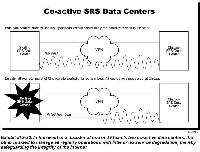
JVTeam is
proposing two co-active data centers for TLD registry operations and a network
of nameservers.� These facilities are geographically
dispersed to minimize the possibility of outages caused by natural or man-made
disasters. The nameservers are dual-homed to each data center via a Virtual
Private network (VPN) backhaul link. As Exhibit III.2-23 indicates, the two
data centers are interconnected by high-speed, alternate-routed VPN links. The
VPN network-management system includes a �heartbeat� signal from each data
center.� If it detects a failed
heartbeat at one data center, it automatically routes all traffic to the other.
Each data center
will have redundant network components, high-availability server clusters, and
fault-tolerant database servers to eliminate single points of failure. All
critical telecommunications access links and network components � e.g.,� routers, firewalls, LAN switches, and server
NIC cards will be redundant. Anything less would be inadequate to provide the
service levels that ICANN and the industry requires.
III.2.11.1��� Defining and Quantifying Quality of Service
JVTeam defines quality of service as the high-availability
aspect of the entire TLD registry
system as perceived by the registrars, registrants, and other end users. In
this context, system availability is a function of both reliability (of
hardware and software components) and performance (response time, throughput,
etc.). Other related factors include system management, diagnostics, and
maintenance; software QA; and database backup and recovery procedures.�
JVTeam has
developed the following list of service level requirements:
Service Availability,
SRS�The amount of time in a
month that registrars are able to initiate sessions with the registry and perform
standard daily functions such as; add a domain name, transfer a domain name,
etc.� JVTeam is engineering the SRS
service for 99.95% availability.
Service
Availability, Nameserver�The
amount of time in a month that internet users are able to resolve DNS queries
to the TLD nameserver network.� JVTeam
is engineering the nameserver service for 99.999% availability.
Service
Availability, Whois�The
amount of time in a month that internet users are able to initiate a Whois
query to the TLD Whois service and receive a successful response.� JVTeam is engineering the Whois service for
99.95% availability.
Update
Frequency, Zone File�The
amount of time it takes for a successful change to zone file data to be
propagated throughout the TLD nameserver network.�� JVTeam is engineering the updates to take place in near
real-time and no longer than 10 minutes.�
An SLR for this service would be crafted in the following manner; 15
minutes or less for 95% of the updates.��
Update
Frequency, Whois�The amount
of time it takes for a successful change to Whois data to be propagated
throughout the TLD Whois Databases.��
JVTeam is engineering the updates to take place in near real-time and no
longer than 10 minutes.� An SLR for this
service would be crafted in the following manner; 15 minutes or less for 95% of
the updates.��
Processing
Time; Add, Modify, Delete�The
time from when the registry receives an add, modify or delete action to when it
acknowledges the action.� JVTeam is
engineering for 500 milliseconds.�
Processing
Time; Query a Name�The time
from when a registry receives a query to when it returns a response.� JVTeam is engineering for 100
milliseconds.�
Processing
Time; Whois�The time from
when the registry receives a Whois query to when it returns a response.� JVTeam is engineering for 300
milliseconds.�
In addition to
these SLRs there should also be SLRs for administrative functions such as
abandonded call rates, scheduled service unavailability notification,
unscheduled service unavailability notification, etc.�
Because these
service levels are so important to ICANN and the internet community JVTeam is
willing to negotiate and report on a regular basis a list of service level
agreements (SLA) with ICANN.� We are
confident that our experience, engineering and operations expertise will
deliver the highest reasonable level of service attainable for such a complex
and important service.�
III.2.11.2��� Analyzing Quality of Service
JVTeam uses system/network-monitoring
capabilities and cluster-management fault-detection services to gather systems
and network performance statistics and to track device/process/interface
availabilities.� The system stores this
data in a local database, then generates a wide variety of pre-programmed and
custom reports that enable us to:
� Track system compliance with SLAs
� Perform performance management and track system performance and resource utilization
� Perform trend analyses
� Perform capacity planning.�
We
will provide ICANN with detailed reports on component availability,
circuit-utilization levels, and CPU loads at the servers and routers. We
summarize performance data and compare it to SLAs.� We will make performance statistics for the previous year available
online; for earlier years, from backups.
For the TLD registry service, JVTeam will also employ the statistics-generating and reporting capabilities inherent in BIND version 9.� BIND 9�s statistics-logging function reports, at selected intervals, the number of queries processed by each server, categorized by query type.� We will automatically collect and generate online reports for ICANN, detailing DNS query/response loads both on individual servers and the entire system.� By deploying application-, systems-, and network-level statistics-collection and capacity-planning tools, JVTeam can provide comprehensive reporting and trending information to ICANN.
III.2.12������ System Outage
Prevention (RFP Section D15.2.12)
The JVTeam�s co-active redundant data centers and high-availability server cluster architecture will maintain continuous operations with no disruptions in service. The benefit to ICANN is improved system availability, minimum downtime, and high confidence in the Internet registry services.
The Internet community requires outage-prevention measures specifically designed to minimize system downtime. Downtime can be categorized as either unplanned or planned:
� Unplanned downtime is caused by failures; e.g., external telecommunications failures, power failures, or internal-network or computer-equipment failures.
� Planned downtime occurs when the system is unavailable due to scheduled maintenance; e.g., software or hardware upgrades and system backups.� Planned downtime is normally minimized in two ways:
- By performing backups, maintenance, and upgrades while the system remains operational (hot)
- By reducing the time required to perform tasks that can be performed only while the system is down.�
In addition to employing the preceding measures for minimizing planned downtime, system designers may use redundancy and high-availability system architectures designed to minimize unplanned outages. Many data-management operations will also have disaster recovery agreements with a business-continuity provider who provides a disaster recovery site geographically separated from the operational data center.� The intent is to maintain continuity of operations in the event of a natural or man-made disaster.
JVTeam believes these approaches alone, although commendable, are insufficient to meet the high service levels expected by ICANN and the registrar community. For example, the registry services are so specialized and component intensive that no business-continuity provider is likely to be capable of resuming services without a lengthy outage period.� We contend that the only way to satisfy the service level requirements is through a combination of approaches, including:
� Co-active redundant data centers with two-way transaction replication
� High availability server cluster architecture
� Hot backup and recovery
� Automated disaster recovery provisions.
Procedures for Problem Detection and Resolution
To best meet data center requirements for availability,
flexibility, and scalability, JVTeam has designed a high availability
architecture that will combine multiple computers into a cluster. Nodes in the
cluster will be loosely coupled, with each node maintaining its own processor,
memory, operating system, and network connectivity. Our
system/network-management and cluster management tools will automatically
detect and compensate for system and network faults and notify system operators.
At five-minute intervals, the
network management system will �ping� network devices with Simple Network
Management Protocol (SNMP) for availability and poll them for performance
statistics.� Event threshold violations
or error conditions will initiate a sequence of alerting events, including
visual notifications via a topology map, an entry into a trap log of event records,
emails to a bulletin board, and notices to technical support staff. The goal is
to detect and repair potential problems before services are disrupted.
An SNMP daemon will be
configured to periodically check the status and health of vital server
processes.� In the event of a critical
process failure, the SNMP agent will send a trap to the network management
system, initiating an alert to the technical support staff.� Our network management software will include
remote monitoring and management of operations, so technical support staff can
easily diagnose and troubleshoot network faults, either from the Network
Operations Center or remotely. Once a problem is detected, it will be resolved
using our proven problem management process. In conjunction with this problem
management process, we will employ proactive performance management and trend
analysis processes to do root cause analysis and discover performance and
utilization trends that could lead to potential problems.
The cluster management software
will organize multiple nodes (up to 16) into a high availability cluster that
delivers application processing support to LAN/WAN attached clients. The
cluster software, which will monitor the health of each node and quickly
respond to failures to eliminate application downtime, will automatically
detect and respond to failures in the following components:
� System processors
� System memory
� LAN media and adapters
� System processes
� Applications processes
� Disk drives.
Since high availability is a primary design goal, a cluster cannot have a single point of failure; accordingly, we will employ RAID mirrored disk drives and multiple LAN connections. The cluster software will monitor these hardware and software component and respond by allocating new resources when necessary to support applications processing. The process of detecting failures and restoring the applications service will be completely automated�no operator intervention will be required.
Redundancy of Data Centers and Systems
JVTeam is proposing redundant co-active data centers: one in Sterling, VA; the second, in Chicago IL. These data centers� will be interconnected by redundant, high-speed, and� secure VPN telecommunications links to provide two-way replication of all registry database transactions. A heartbeat monitor will determine the on-line status of each data center and enable the services be provided entirely from the second data center if one is lost.
Within each data center, the system will be redundantly configured so that failure of any system component will leave a configuration of surviving system components capable of executing the entire workload within 95 percent of the previous performance for at least 90 percent of users.� To achieve no-single-point-of-failure architecture, JVTeam will replicate all components and configure the system for automatic failover.
The following table describes system architecture redundancy we will employ at each SRS data center to meet 99.9+ percent service availability levels.
|
SYSTEM REDUNDANCY ELEMENTS |
||
|
Issue |
Redundancy Solution |
Benefit |
|
Single failure of a
system component |
Replicate all critical
components to eliminate single point of failures |
The system is capable of
executing the entire workload. |
|
Maintaining availability
of applications |
Stateless N+1 node high-availability
processor clusters |
In event of a processor
failure, service is not degraded. |
|
LAN Interface or Cable
Failure |
Multi-Path LAN I/O |
Automatic switchover from
one LAN switch to another to restore connectivity |
|
Disk-controller or cable
failure |
Multi-path Disk I/O |
Applications take
alternate routes |
|
Disk-storage-module
failure |
Redundant Array of
Independent Disks (RAID, levels 1, 3, and 5) |
Applications still have
access to data in the event of a single disk failure |
|
Hardware/software
upgrades and additions or changes to the configuration |
N+1 Redundancy allows hot
repair/upgrade of system components. |
Eliminate downtime due to
administrative and maintenance tasks |
|
Dynamic processor
de-allocation |
Dynamically take a
processor out of service to modify the physical and logical configuration of
the system. |
Eliminate downtime due to
maintenance tasks and component replacement |
|
Replace disks |
RAID drives and
controllers allow hot plug in of disk modules |
Eliminate downtime due to
maintenance tasks |
Hot Repair of System Components
Another advantage of system redundancy is that it will enable our maintenance staff to use hot repair replacement of system components. Keeping the system in full operation while we perform such common system-administration tasks as upgrading the hardware or software or adding to or changing components will eliminate the MTTR (Mean-Time-To-Repair) factor and will minimize downtime. Hot repair is only possible when major system components are redundant, as in the JVTeam solution.
Backup Power Supply
Each SRS and nameserver data center will be provided with UPS power to ride through brief electrical transients and outages.� For more than brief outages, each data center will have a 250 KVA motor-generator capable of running the entire data center in the event of a more lengthy electrical blackout.
Facility Security
As discussed in Registry Operator�s Proposal Section
III.2.9, JVTeam will vigorously enforce physical-security measures, controlling
all access to our facilities.�
Throughout normal working hours, security personnel stationed at each
building entrance will verify that employees are displaying proper
identification badges and control access by non-employees.� Non-employees must sign in to gain entrance;
the sign-in books will be stored for a period of one year.� If the purpose of a non-employee�s visit is
found to be valid, he or she will be issued a temporary badge; otherwise,
entrance will be denied. At all times while they are in the facility, visitors
must display their badges and must be escorted by a JVTeam employee.� We will also strictly enforce the policy
that employees wear their badges prominently displayed at all times while in
the facility. During off-hours (6:30pm to 6:30am and
all day on weekends and major holidays), individuals must use the
proper-electronic key cards to gain access to the building.� We will issue electronic-key cards only to
employees who need access for business purposes.
In addition to being stationed
at building entrances during normal working hours, on-site security personnel
will be on duty 24 hours a day and 7 days a week to monitor the images from
closed-circuit television cameras placed strategically throughout the
facilities.� Further, any room housing
sensitive data or equipment will be equipped with a self-closing door that can
be opened only by individuals who activate a palm-print reader.� Senior managers will establish the rights of
employees to access individual rooms, and ensure that each reader is programmed
to pass only those authorized individuals.�
We will grant access rights only to individuals whose duties require
them to have hands-on contact with the equipment housed in the controlled
space; administrative and customer-service staffs normally do not require such
access.� The palm readers will compile
and maintain a record of those individuals who enter controlled rooms.�
The following table lists our
physical-security mechanisms.
|
PHYSICAL-SECURITY PROVISIONS |
|
|
Mechanism |
Purpose |
|
Security guards |
Physically prevent
intruder access; verify employee badges |
|
Closed-circuit
video-surveillance cameras |
Extend capabilities of
security guards; maintain access records |
|
Intrusion-detection
systems |
Extend capabilities of
security guards to building perimeter |
|
Identity badges |
Permanent
badges for employees; easily recognizable temporary badges for visitors |
|
Sign-in registers |
Maintained as permanent
records for at least one year |
|
Electronic-key badges |
Control physical access
during off-hours; maintain access records |
|
Palm readers |
Restrict physical access
to mission-critical rooms within our facilities; maintain access records |
|
Self-closing doors |
Restrict physical access
to mission-critical rooms within our facilities |
Technical Security
Registry Operator�s Proposal Section III.2.9 also describes the technical security measures that JVTeam proposes.� We will use the underlying user-id and password security features of the XRP, supplemented by system-based Public Key Infrastructure (PKI) services to provide additional security. The following table lists the systems, protocols, and devices to prevent system hacks, break-ins, data tampering, and denial-of-service attacks.�
|
DATABASE AND OPERATING-SYSTEM SECURITY |
|
|
Technical Security-System
Element |
Features and Benefits |
|
C2 access-control
system:� User ID and password, file
level access control lists |
Ensures that the user can
access authorized functions, but no others, and can perform only authorized
operations within these functions.�
For example, the registrar of a registered domain name is authorized
to query it and then renew or cancel it or change its nameservers, but cannot
query domain names held by other registrars. |
|
Database: User ID and
password; user profiles |
�
Limits database access to pre-authorized users. �
Retains the last two passwords and disallows their usage. �
Rejects simultaneous sessions by an individual user. �
Stores user profiles. �
Limits access rights to database objects and functions to
a specified user or user group. �
Rejects unauthorized access attempts.� Automatically revokes identification codes
after a pre-established number of unsuccessful attempts. �
Provides an interface to facilitate the on-line administration
of user privileges. |
|
ECommerce-Security
Features |
|
|
SSL v3.0 protocol |
HTTPS encryption ensures
that messages between the registry and registrars can be read only by the
intended receiver. |
|
Digital signatures |
Issued by an X.509
authentication server, digital signatures ensure that the incoming data
actually has come from the purported sender; provides non-repudiation. |
|
Boundary-Security
Features |
|
|
Router |
Permits only DNS UDP/TCP
packets to enter the data center LAN, thus isolating the TLD system from most
potentially damaging messages. |
|
Firewall |
Guards the secure TLD LAN
from the non-secure Internet by permitting the passage of only packet flows
whose origins and destinations comply with pre-established rules. |
|
Intrusion Detection |
Detects intrusion at the
LAN level.� Displays an alert at the
TLD network-operations workstation and creates a log entry. |
Availability of Backup Software, Operating System, and Hardware
Registry Operator�s Proposal Section III.2.7 describes our zero-downtime/zero-impact backup process, which will use backup servers, disk array, and a DLT robotic-tape library.� The dedicated backup system will be independent of the registry server clusters that run the applications.
System Monitoring
The subsection entitled �Procedures for Problem Detection and Resolution� describes system-monitoring capabilities and procedures.� Our Network Management System and specialized element managers will monitor specific routers, LAN switches, servers cluster, firewalls, applications, and the backup servers.� In addition, the cluster-management software will monitor the status and health of processor, memory, disk, and LAN components in the high-availability cluster.
Technical Maintenance Staff
The JVTeam 3-tier customer service approach will ensure that all problems are resolved by the appropriate party in a timely manner.�
The Technical Support Group will operate out of the Help Desk Network Operations Center (NOC) within the data centers.� The group will be comprised of system administrators, network administrators, database administrators, security managers, and functional experts in the TLD registry IT systems and applications infrastructure.� Registrars access the Technical Support Group through the Tier-1 Help Desk.� This group will resolve trouble tickets and technical problems that have been escalated to them by the Help Desk Customer Service Agents. If the problem involves a hardware failure, the Technical Support Group will escalate the problem to our Tier-3 on-site maintenance technicians, third-party maintenance providers, or our hardware vendors, depending on the nature of the problem.
Server Locations
JVTeam�s registry servers will be located in the SRS data centers in Sterling, Virginia, and Chicago, Illinois.� Two zone nameserver centers will be co-located with the registry data centers; the remaining nameserver centers will be geographically dispersed with dual-homed telecommunications links and redundant high-availability servers to provide resilience and disaster recovery.
III.2.13������ System Recovery Procedures (RFP Section D15.2.13)
JVTeam is
proposing two co-active SRS data centers and a network of nameserver data
centers geographically dispersed to provide redundancy and to enable us to
responsibly recover from unplanned system outages, natural disasters, and
disruptions caused by human error or interference. ICANN and the Internet
community can be confident that we will respond to unplanned system outages
quickly with little or no loss of services.
To maintain public confidence in the Internet, ICANN requires a high level of system-recovery capabilities.� Proven industry solutions to the problems of outages and disaster recover incorporate high-availability system architectures and fast failover from the primary data center to a mirrored-backup.� High-availability solutions minimize downtime, with availability of 99.9 percent or greater. Continuously available solutions go a step further, with virtually zero downtime creating an availability of approximately 99.999 percent (five nines).
System-recovery architectures include:
� Symmetric Replication�The database replicate (on the backup or failover system) is identical to the primary database on the production system because any change made to the primary database is �replicated� in real time on the backup database. Since this is not a �two-phase commit� process, a small window of vulnerability exists, during which changes made to the primary system could be lost in transit.� Replication may increase transaction times, but switching from the primary database to the backup can be very fast and essentially transparent to end-users.
� Standby Databases�This is a special case of replication.� A standby database at a backup site originates as an identical copy of the primary database. Changes (updates, inserts, deletes) to the primary database are recorded in transaction logs that are periodically archived. Archived logs are delivered to the backup site and applied to the standby database. In a best-case scenario, the standby system is behind (in terms of data currency) the primary system by the number of changes contained on the current transaction log.
� Remote Data Mirroring�This is the classic disk-mirroring procedure, except conducted at a long distance. Depending on whether hardware or software mirroring is used, the performance impact can vary from minimal to significant. Switchover to the backup site can be quick and virtually transparent to end-users. The loss of data is zero, although a �system crash� type of database recovery is needed.
JVTeam�s system-recovery solution is based on running mission-critical SRS applications at two co-active data centers, separated by nearly 700 miles, with database-replication technology that maintains database synchronization between the two centers. To provide backup for DNS queries, we are implementing multiple nameserver data centers, also physically separated by long distances. We recognize that system management and recovery are more difficult when the system spreads over a large geographical area; however, two-way replication between the co-active SRS data centers will keep the registry master databases identical.�
III.2.13.1��� Restoring SRS Operations in the Event of a System Outage
Believing that prevention of failure is better than restoring after failure, to maximize availability and eliminate the possibility that a single-point failure could shut down operations, we implemented each of the co-active SRS data centers and four zone nameservers with:
� Redundant components with no single point of failure
� High-availability cluster architecture
� Load balancers, which are used primarily to distribute the processing load across multiple servers, defend against common denial-of-service attacks that can precipitate outages caused by processor overloads
� Fault-tolerant hardware
� Data backup/restore systems that work together to avoid unplanned outages.� (Naturally, the primary function of these systems remains quick recovery, should such an outage occur.)
The recovery mechanisms we will implement include:
� Full backup and continuous, incremental backup CD ROMs and DLT Tapes are maintained at the data center and at the secure escrow facility.� These backups enable us to recover, rebuild, and return to operation the operating system, application software, and databases.
� Processor nodes in the cluster are monitored (and controlled) by cluster-management software to facilitate recovery of software applications in the event of a processor failure.
� In the event of a database failure, fault-tolerant database software fails over to the replicated backup database, enabling applications using database services to recover operations seamlessly.
� Processors in high availability clusters have dual attach ports to network devices and RAID disk arrays, enabling them to recover from a failure in a single port or disk drive.
� Our high availability clusters are sized to run at peak load. If a processor fails, the excess capacity in the cluster handles the full processing workload while the failed node is repaired or replaced.� In essence, this is instantaneous recovery.
The remainder of this subsection describes how we would recover from a system-wide disaster; e.g., one that disables an entire data center. Subsection III.2.13.3 discusses recovery from various types of component failures.�
Each of the co-active data centers is sized to take over the entire load of the SRS operations, and each zone nameserver is dual-homed to each data center.� With this architecture, recovery in the event of a disaster is nearly instantaneous. Sessions that were dropped by the data center that suffered the disaster are simply re-started on the remaining data center within seconds. The main issues that our disaster-recovery strategy solves include:
� Instead of having a primary and a backup data center, we use two co-active data centers whose data and applications are kept synchronized by two-phase commit replication.� Because the XRP servers are configured to retry failed transactions, neither registrars nor users submitting queries will perceive any degradation in service.�
� If a data center goes off-line, the workload is transparently switched to the remaining data center.� The transaction latency is limited to the brief time needed to replicate the last transaction to the surviving data center.
� Two-way replication of transactions between the sites keeps each site�s databases in a state of currency and synchronization that is consistent with mission critical availability levels.
The use of co-active data centers with two-way replication between them provides fast, simple disaster recovery that maintains continuity of operations � even in the event of a major disaster. The resulting zero-downtime/zero-impact system not only solves system recovery problems, it also sustains confidence in the Internet.� The following are the procedures that are followed to restore operations if an SRS or nameserver data center experiences a natural or man-made disaster:
� SRS or nameserver operations are immediately failed over to the co-active data centers; registry operations proceed uninterrupted, except for those transactions that were in transit between the two centers.
� We implement the disaster recovery plan for the failed data center and place the disaster recovery team on alert.
� Within eight hours, the disaster recovery team is assembled and dispatched to the failed data center to help the local data center personnel stabilize the situation, protect the assets, and resume operations.
� The disaster recovery team assesses whether the building housing the data center can be used to recover operations.
- If so, the team contacts disaster recovery specialist firms under contract to JVTeam to secure the facility and begin recovery operations.
- If not, the team salvages equipment and software assets to the extent possible and procures an alternate data-center facility. JVTeam initiates its contingency plan to reconstruct the data center in the new location, repair and test the salvaged equipment and software, and procure the remaining required components with quick-reaction procedures.
� Once the disaster recovery team has stabilized and tested the SRS or nameserver equipment, it retrieves the system and application software CD ROMs and the database backup tapes from the secure escrow.� It then rebuilds the data center using the same recovery procedures that are used restoring components lost in a more limited failure. (Subsection III.2.13.3 describes these procedures.)
III.2.13.2��� Redundant/Diverse Systems for Providing Service in the Event of an Outage
JVTeam is proposing two co-active SRS data centers and multiple zone nameserver data centers with high availability clusters and cluster management software that enables multiple node processors, in conjunction with RAID storage arrays, to quickly recover from failures.� The server load balancer and the cluster manager software monitor the health of system processors, system memory, RAID disk arrays, LAN media and adapters, system processes, and application processes.� They detect failures and promptly respond by reallocating resources.
Dual fault-tolerant database servers are coupled to a primary and a backup database and RAID configuration to ensure data integrity and access to the database. The database system uses synchronous replication, with two-way commits to replicate every transaction to the backup database. The process of detecting failures and restoring service is completely automated and occurs within 30 seconds with no operator intervention required.�
III.2.13.3��� Process for Recovery From Various Types of Failures
The following table lists the possible types of failures and describes the process for recovery.
|
FAILURES AFFECTING THE ZONE NAME SERVER SITES |
|
|
Failure Type |
Recovery Process |
|
Nameserver cluster processor
fails |
Cluster management
software logs out the failed processor and processing continues on the
remaining nodes in the cluster. |
|
Internet or VPN link
fails |
Ongoing sessions are
dropped and restarted on the other redundant ISP or VPN-access link Ongoing sessions are
dropped and restarted on one of the other nameserver sites |
|
Edge Router, Firewall, or
Load Balancer Fails |
Ongoing sessions are
dropped and restarted on the redundant components. |
|
FAILURES AFFECTING THE DATA
CENTER APPLICATIOINS AND DATABASE SERVER |
|
|
Failure Type |
Recovery Process |
|
Applications-cluster processor
fails |
Cluster management
software logs out the failed processor and processing continues on the
remaining processors in the cluster. |
|
XRP server processor
fails |
Registrar session is
dropped from the failed server and restarted on the other XRP server |
|
Web server processor
fails |
Cluster management
software logs out the failed processor and processing continues on the
remaining processors in the cluster. |
|
Database server processor
fails |
The operating system
automatically distributes load to the remaining SMP processors |
|
Database disk drive fails |
Processing automatically
continues on the RAID with no data loss |
|
Database crashes |
The applications
processing seamlessly continues on the backup replicate database |
|
Authentication server
fails |
Processing automatically
continues on the redundant authentication server |
|
Whois-cluster processor
fails |
Cluster management
software logs out the failed processor and processing continues on the
remaining processors in the cluster |
|
A Billing server fails |
Processing automatically
continues on the redundant B&C server |
|
Internet or VPN link
fails |
Ongoing sessions are
dropped and restarted on the other redundant ISP or VPN-access link |
|
Router or firewall fails |
Ongoing sessions are
dropped and restarted on the remaining redundant router or firewall. |
In all cases of component failure, system recovery is automatic, with zero downtime and zero impact on system users.� The remainder of this subsection (III.2.13.3) provides additional information about failure recovery considerations for individual components.
Recovery From a Cluster Processor Failure
If one processor in a cluster fails, the cluster manager software logically disconnects that processor. While technicians repair or replace it, applications and user sessions continue on the remaining cluster processors. After the failed processor is off-line, the following procedures are used to recover it:
1. Testing and troubleshooting with diagnostic hardware and software to determine the root cause (e.g., hardware [CPU, memory, network adapter] or software [system or application subsystem])�
2. Repairing hardware failures and, if necessary, rebuilding system and applications software from the backup CD ROM
3. Testing the repaired processor and documenting the repairs in the trouble ticket
4. Logging the processor back into the cluster.
Database System Recovery
Our database-management system supports continuous operation, including online backup and management utilities, schema evolution, and disk space management. All routine database maintenance is performed while the database is on line.
JVTeam�s fault-tolerant database server software solution will provide distributed redundancy by implementing synchronous replication from a primary database server to a backup database server. This solution includes automatic and transparent database fail over to the replicated database without any changes to application code or the operating system.
If a database-system node experiences a hardware failure or database corruption, JVTeam technicians use the following recovery procedures:
1. Test and troubleshoot with diagnostic hardware and software to determine the root cause (e.g., hardware [CPU, memory, network adapter, RAID disk array] or software [operating system, database system, monitoring software])
2. Repair hardware failures and, if necessary, rebuild operating system and applications software from the backup CD ROM.
3. Test the repaired processor and document the repairs in the trouble ticket.
4. Restore the data files by applying (in the correct sequence) the full backup DLT tapes and the incremental backup DLT tapes maintained in the data center
5. Log the processor node back into the fault-tolerant server configuration and synchronize the database by applying the after-image journal files until the primary and replicate database are fully synchronized. The procedure is as follows:
� Recreate the database directories and supporting file structure
� Insert the full backup tape from the escrow facility and restore the base level backup.
� Insert incremental backup tapes in the correct order to ensure they are correctly applied to the base level backup.
� Using the log roll forward recovery, mount the roll forward recovery tapes and apply them to the database.
III.2.13.4��� Training of Technical Staff Who Will Perform Recovery Procedures
JVTeam technical personnel have an average of five years of data-center operations experience, encompassing the high-availability cluster technology, distributed database management systems, and LAN/WAN network management systems that are employed in the recovery process. New hires and transfers to JVTeam�s TLD registry operations will be given the following training:
� A one-week �TLD Registry Overview� course
� Vendor offered courses for certification in backup/recovery, cluster management, system management, and network management
� On-the-job training on registry operations, including high availability cluster management, system backup/recovery, database backup/recovery, and system/network management.
III.2.13.5��� Software And Operating Systems for Restoring System Operations
JVTeam will use commercially available Unix operating
systems, cluster management software, and backup/recovery software to restore the
SRS and nameserver systems to operation.�
In addition to providing synchronous replication of registry
transactions to the backup server, our database-management system will provide
data recovery services using the DLT tape backup system.� Backup/recovery hardware and software at the
SRS data center will remotely back up and restore the nameservers over the VPN.
All static applications software and operating systems are backed up to DLT tape volumes and converted to CD ROM for quick restoration in the event of operating system or application software failures. Backup copies are maintained in the data center for quick access, with additional copies in the secure escrow facility.
III.2.13.6��� Hardware Needed to Restore and Run The System
The two co-active data centers will house the commercial off-the-shelf, fault-tolerant cluster servers and dedicated backup/recovery servers that are needed to restore the system to operation.
III.2.13.7��� Backup Electrical Power Systems
Each of the two data centers is configured with a UPS battery-backup system that provides sufficient power for 30 minutes of operation.� They also have a transfer switch connected to 1000-KVA motor generators that are capable of powering the entire data center for many days without commercial power.
III.2.13.8��� Projected Time for Restoring the System
Two co-active data centers, each with high-availability clusters sized to handle the full projected registry load, provide the SRS services.
� If an individual cluster experiences a processor failure, that processor�s applications are transferred to another processor within approximately 30 seconds; however, the remaining processor nodes in the cluster continue applications processing without interruption.
� Since there are two co-active data centers with two-way database replication to maintain database synchronization, even if a natural or man-made disaster eliminates one data center, registry services continue with zero downtime and zero impact on users.� The only impact is transitional, with dropped sessions to the RP server, Whois Server, and Name Servers.� Because the protocols reinitiate a failed transaction, even these operations are fully restored in less than 30 seconds with no loss of data or transactions.
III.2.13.9��� Testing the System-Restoration Process
JVTeam will test disaster recovery plans and outage
restoration procedures annually to ensure that they can effectively restore system
operations.
III.2.13.10� Documenting System Outages
System-problem documentation includes the following:
�
The system manager and network manager systems collect
performance and utilization statistics on system processors, system memory, LAN
media and adapters, routers, switches, system processes, and applications
processes.�
�
The automated help desk database contains documentation
on trouble tickets, whether system generated or generated by the Help Desk
�
The trouble ticket database contains the documentation
of the steps taken to resolve trouble tickets
�
The data center manager collates, analyzes, and reports
monthly statistics on help desk activities, system utilization and performance,
and outages.� �
III.2.13.11� Documenting System Problems that Could Result in Outages
JVTeam�s proactive systems management processes include performance management, trend analysis, and capacity planning. These processes analyze system performance and utilization data to detect bottlenecks and resource utilization issues that could develop into outages. Monthly reports on the three processes keep the data center manager appraised of our performance against service level agreements and raise awareness of potential problems that could result in outages.
In addition, JVTeam performs root cause analysis of hardware and software failures to determine and analyze the reason for any failure. Based on our findings, we work with vendors to generate hardware service bulletins and software maintenance releases to prevent re-occurrence of these failures.
III.2.14������ Technical and Other Support (RFP Section D15.2.14)
In addition to maintaining our central Help Desk and technical-support team, JVTeam will offer Web-based self-help support via the tld.JVTeam.TLD portal. This enables registrars to access our domain-name-application process, a knowledgebase, and frequently asked questions.
ICANN requires technical support for the rollout of any new TLD registry services, as well as for continuous registry operations. This technical support must satisfy several criteria:
� It must support all ICANN-accredited registrars
� To support the world�s different time zones, access must be available worldwide, 7x24x365
� It must accommodate the anticipated �Land Rush� when the new TLD names are opened for registration.
The ICANN registry model provides a clear, concise and efficient deliberation of customer support responsibilities. Registrars provide support to registrants and registries provide support for registrars. This allows the registry to focus its support on the highly technical and administratively complex issues that arise between the registry and the registrar.
III.2.14.1��� Technical Help Systems
Registrars have a great deal of internal technical capability because of their need to support an IT infrastructure for their marketing and sales efforts and for their customer-support and billing-and-collection services.� JVTeam will enhance these registrar capabilities by providing the registrars with the following types of technical support.� All will be available on a 24 x 7 x 365 basis. The JVTeam will make their best effort to provide service in multiple languages.� The services are:
� Web-based self-help services, including:
- Knowledge bases
- Frequently asked questions
- White papers
- Downloads of XRP client software
- Support for email messaging
� Telephone support from our central Help Desk
� Fee-based consulting services.�
Web Portal� (tld.jvteam.tld)
JVTeam will implement a secure Web-based multimedia portal to help support registrar operations. To obtain access to our Web-based services, a registrar must register his registrants with us, and must have implemented our security features, including SSL encryption, log in with user ID and password, and digital certificates for authentication.
The home page of the web portal will include a notice to registrars of planned outages for database maintenance or installation of software upgrades.� This notification will be posted 30 days prior to the event in addition to active notification including phone calls and email.� We will also record outage notifications in the help desk database to facilitate compliance with the service-level agreement. Finally, seven days and again two days prior to the scheduled event, we will use both an email and a Web-based notification to remind registrars of the outage.�����
Non-affiliated registrars and the general Internet community may obtain generic information from JVTeam�s public Web site, which will describe our TLD service offerings and list ICANN-certified registrars providing domain-name services.
Central Help Desk
In addition to implementing the Web site, we will provide telephone support to our registrars through our central Help Desk. Access to the help desk telephone support is through an automatic call distributor that routes each call to the next available customer support specialist.� We will authenticate callers by using caller ID and by requesting a pre-established pass phrase that is different for each registrar.� Requests for assistance may also come to the Help Desk via email, either directly or via the secure Web site.�
The Help Desk�s three tiers of support are:
Tier-1 Support�Telephone support to registrars who normally are calling for help with customer domain-name problems and such other issues such as XRP implementation or billing and collection. Problems that can�t be resolved at Tier 1 are escalated to Tier 2.
Tier-2 Support�Support provided by members of the technical support team, who are functional experts in all aspects of domain-name registration.� In addition to resolving escalated Tier 1 problems with XRP implementation and billing and collection, Tier 2 staff provides technical support in system tuning and workload processing.�
Tier-3 Support�Complex problem resolution provided by on-site maintenance technicians, third party systems and software experts, and vendors, depending on the nature of the problem.
In turn, the Help Desk uses an automated software package to collect call statistics and record service requests and trouble tickets in a help desk database.� The help desk database documents the status of requests and tickets, and notifies the Help Desk when an SLA threshold is close to being breached.� Each customer-support and technical support specialist uses our problem management process to respond trouble tickets with a troubleshooting, diagnosis, and resolution procedure and a root-cause analysis.
Escalation Policy
Our escalation policy defines procedures and timelines for elevating problems either to functional experts or to management for resolution if they not resolved within the escalation-policy time limits. The following table is an overview of our escalation policy.
|
Level |
Description |
Escalation
Policy |
Notification |
|
I |
Catastrophic outage affecting
overall registry operations |
Data-center manager
escalates to JVTeam management and Disaster-Recovery Team if not resolved in
15 minutes |
Web portal and e-mail
notifications to all Registrars within 15 minutes; updates every 30 minutes |
|
II |
Systems outage affecting
one or two registrar sessions but not the entire system |
Systems engineer
escalates to data-center manager if not resolved in one hour |
Web-portal notification
to all registrars; hourly updates |
|
III |
Technical questions |
Help Desk
customer-support specialist escalates to the systems engineer if not resolved
in two hours |
Hourly updates to registrar
via e-mail |
|
IV |
Basic questions |
Help Desk customer-support
specialist escalates to the systems engineer if not resolved within four
hours |
Hourly updates to registrar
via e-mail |
III.2.14.2��� Staffing
Initially, JVTeam will staff its Help Desk with a complement of customer service specialists, enabling us to operate three shifts providing 24 x 7 x 365 coverage. We will add staff as necessary to respond to incoming requests within the service-level agreement.� Customer-service specialists will obtain assistance from JVTeam�s technical staff for any problems that cannot be resolved in one phone call.
III.2.14.3��� Test� and Evaluation Facility
JVTeam will establish an operational test-and-evaluation facility that will be available 24 x 7 x 365 for registrars to test their client XRP system. Our technical-support team, which consists of functional experts in the processes and technologies for domain-name registration, will support the registrars� testing.
Once each new registrar is satisfied that its system is compatible with the registry system, it will schedule a formal acceptance test that will be monitored by our system engineer. After a registrar has passed the acceptance test, we will issue its user id, passwords, and digital certificates, and the registrar can begin operations.
III.2.14.4��� Customer Satisfaction Survey
To determine registrars� satisfaction with registry services, JVTeam will implement a Web-based customer-satisfaction survey that will consist of a set of survey questions with responses ranging from one to five on the Likert Scale.� We will tabulate the results and publish them on the Web site.
To further verify the quality of our customer services, JVTeam will commission a biannual customer-satisfaction survey by an independent third party.