Table of contents:
SECTION D – PART
III - TECHNICAL CAPABILITIES AND PLAN
D15.1 Detailed description of the registry operator's technical
capabilities.
Internet experience and database operations
Data protection and Intellectual Property rights
Access to system development tools
D15.2.1 General description of proposed facilities and
systems
Deployment diagrams and system realization
In-house
registrar service component
Physical diagrams and structures
General information about the hardware
Entry point for Accredited Registrars
External data-centers for DNS and WHOIS
Database description and structure
Location, connectivity and environment descriptions
D15.2.2 Registry-Registrar Protocol and interface
A new,
Stateless Registry-Registrar Protocol
Attribute/value
set definitions
Mapping from SRRP to the RRP as defined in RFC 2832
Mapping
multiple RRP-commands on to one SRRP-command
Handling
name server clusters through RRP
Handling
unsupported RRP commands
Database software, hardware and performance
Domain transfers in the database
D15.2.5 Zone file distribution
Software diversification on DNS
D15.2.6 Billing and collection systems
D15.2.7 Data escrow and backup
Software and hardware security
Software and Hardware Encryption
Intrusion Detection System(IDS) and Intrusion Response
Team(IRT)
Physical security of the facilities
D15.2.12. System outage prevention
D15.2.13 System recovery procedures
Fast recovery in case of single server failure
Recovery in case of full or partial data center
destruction
D15.2.14. Technical and other support.
Table of Figures:
Figure 1: Use case top level
diagram
Figure 2: Detailed view of
"DomainHandling" use case
Figure 3:Activity diagram realizing
the "InsertNewDomain" use case, activity view
Figure 4:Sequence diagram realizing
the "InsertNewDomain" use case, control view
Figure 5:Activity diagram realizing
the "UpdateDomain" use case, activity view
Figure 6:Sequence diagram realizing
the " UpdateDomain " use case, control view
Figure 7:Activity diagram realizing
the "DeleteDomain" use case, activity view
Figure 8:Sequence diagram realizing
the " DeleteDomain " use case, control view
Figure 9:Activity diagram realizing
the "TransferDomain" use case, activity view
Figure 10:Sequence diagram
realizing the "TransferDomain " use case, control view
Figure 11:Detailed view of
"ApplyForDomain " use case (from figure 1 - main use case diagram
Figure 12:Sequence diagram
realizing the “ApplyForDomain" use case, control view
Figure 13:Detailed view of
"RegistrarAccountAdmin" use case (from figure 1 - main use case
diagram
Figure 14:Package diagram of the
system components
Figure 15: Registrar client
component
Figure 16: Deployment diagram of
the Registrar client component
Figure 17: Command handler
component
Figure 18:Deployment diagram of the
command handler component
Figure 19: Distribution component
Figure 20:Deployment diagram of the
distribution component
Figure 21: Registry data component
Figure 22: Deployment diagram of
the registry Registry data component
Figure 24:Deployment diagram of the
registry Registry data component
Figure 26:Deployment diagram of the
Registry data component.
Figure 27: In-house Public services
Figure 28:Deployment diagram of the
in-house public services component
Figure 29: Offsite public services
Figure 30: Deployment diagram of
the offsite public services component
Figure 31: In-house registrar
service component
Figure 32: Deployment diagram of
the in-house registrar Registrar service component
Figure 33: Hardware deployment in
the main data centre
Figure 34: Software high level
structure
Figure 35: Database ER diagram
Figure 50: The ER diagram of the
database
Figure 53:Logical map of the
distribution of the zone files (and WHOIS)
Figure 54: The storage facility
location of Sourcefile
Figure 55: Usage of the WHOIS
system
Figure 56: Distribution of the
WHOIS data
D15.1 Detailed description of the registry operator's technical capabilities.
This should provide a detailed description of the Registry
Operator's technical capabilities, including information about key technical
personnel (qualifications and experience), size of technical workforce, and
access to systems development tools. It should also describe the Registry
Operator's significant past achievements. This description offers the Registry
Operator an opportunity to demonstrate the extent of its technical expertise in
activities relevant to the operation of the proposed Registry
The Global Name Registry (GNR) was established by Nameplanet.com for the purpose applying for and operating a personal delegated TLD. It is established as a completely separate entity to ensure that no possibility of conflict of interest could occur. As a consequence, GNR has no current ongoing operations. However, Nameplanet.com has extensive experience in areas relevant to the Registry and therefore a number of key personnel will be transferred to GNR. The following pages detail the experience that these GNR resources will be bringing from Nameplanet.com
Experience to be transferred:
·
Has
successfully acquired 700,000 users after 8 months of operations, who are all
using a personal domain name for a web-mail and web-page solution fully
developed and operated in-house.
·
Currently
operating an IBM 2.3 Terabyte ESS backend system, and a high availability
active-active failover front-end system
·
Real-time
encrypts private information.
·
The
current system is handling more than 10,000 registrations day, with thousands
of simultaneous users.
·
Extensive
experience with backup, which is taken daily and transported offsite.
·
Extensive
experience with running DNS, since the company is handling the full DNS service
for the personal domains of all 700,000 users.
·
Has
entered into strategic technical partnership with IBM and minimized variations
in equipment used.
·
Has
ensured 99.8% uptime since service was launched February 1.
DNS experience
Nameplanet.com has as its core proposition to end users the free usage of a domain name that corresponds to the user’s personal name for email and web page purposes. To be able to offer this service, Nameplanet.com has acquired extensive statistics about the most common last names in the world, for each of the countries in which the service is launched. A large number of domain names identical to the most common last names have then been purchased on different TLDs to be shared among different users, each using it for free. The result is that domain names are being shared among people with equal interests in it, i.e. Ken Williams and Sven Williams can both use the domain name williams.TLD for their personal purpose, instead of it being held by one user only.
To keep track of all domain names covering the last names of roughly 210 million people in the US only, as well as the DNS functionality of hundreds of thousands of domain names, Nameplanet.com has developed a custom database for administering the DNS servers, renewals, MX records etc. on the massive amount of domain names in use by currently more than 700,000 users, growing at 5% a week. This database makes Nameplanet.com confident that all possible actions are taken to ensure a stable operation of the domain names that the end users rely on. Large efforts have been deployed to ensure that all DNS updates, maintenance and transfers of data to DNS servers are done securely and without loss of functionality of the vital DNS servers.
Nameplanet.com has through its operations in the DNS space accumulated knowledge and contacts within the arena, both through commercial relationships with several Registrars, ccTLD managers, DNSO and ICANN. Participation at the ICANN Board meetings have given insight into the policies and operations of the DNS community and valuable experience.
Internet experience and database operations
The users of Nameplanet.com register online and immediately get assigned an address of the type firstname@lastname.com and a web page www.firstname.lastname.com, or other TLDs where the .com-version has not been available. Nameplanet.com has developed fully in-house a custom object-oriented database for the webmail users, and has ensured 99.8% uptime since launch in Februray 2000. This custom database currently serves thousands of simultaneous users, and has done tens of thousands of email account and web page account registrations per day. The high-performance web-servers and storage solutions scale to millions of users, and are handling increasing data volumes.
Data protection and Intellectual Property rights
By operating a web mail solution for 700,000 people, Nameplanet.com has taken very strong precautions in order to deal properly with the user private data, both technically and legally, in terms of storage, encryption, backup, protection and Intellectual Property rights in various jurisdictions.
Nameplanet.com has strong expertise of Intellectual Property rights with regards to domain names, as it has thoroughly investigated the risk of the business of sharing a domain name between people with the same last name. This expertise also applies to the UDRP as well as national Intellectual Property law of the US and major European countries.
Access to system development tools
The tech team has access to the system development tools needed for implementing high end web based applications. Most of the systems at Nameplanet.com are written in object oriented C++ in a way that makes them highly portable across platforms.
The code is close to being POSIX.1 compliant, and should compile with no or small modifications on any POSIX.1 supporting platform with an ANSI C++ compiler. Only minor modifications would be required in a few low level modules to support non-POSIX.1 compliant systems, provided an ANSI C++ compliant compiler is available. The GNU/FSF tools automake and autoconf are used to provide solid, well tested configuration management for multiple platforms.
As backend database solutions, Nameplanet.com uses Oracle for systems requiring a high degree of updates, CDB for system requiring fast hash lookups, and an object oriented database built in-house for storing XML fragments distributed in (possibly heterogenous) clusters.
Nameplanet.com has spent considerable resources on building a web framework that can scale through distributed operation, caching and mirrors of critical content. The systems are well tested, as parts of Nameplanet.com’s current webmail service, and automated testing suites are in development for the core functionality.
D15.2.1 General description of proposed facilities and systems
General description of proposed facilities and systems.
Address all locations of systems. Provide diagrams of all of the systems
operating at each location. Address the specific types of systems being used,
their capacity, and their interoperability, general availability, and level of
security. Describe in detail buildings, hardware, software systems,
environmental equipment, Internet connectivity, etc.
This chapter presents goes through the systems and technical facilities that constitute the Registry, from use-case modelling and sequence diagrams, to deployment diagrams and hardware structure. The chapter is meant to be comprehensive, although some parts of the system are more detailed in subsequent chapters.
High-level system description
Figure 1: Use case top level diagram
The core functionality of the system is centred around the Registry. The Registry is responsible for administrating one or more top level domains (e.g. .name). All main use cases are in some way involved in the handling of these top-level domains. In the following we will give a brief description of all the main actors and use cases identified in figure 1.
Actors:
|
|
Registry: This is the organization responsible for administrating one or more top-level domains. By organization we mean the technical as well as organizational infrastructure built to support this business. |
|
|
RegistrarClient: A RegistrarClient is an organization acting as a domain buyer on behalf of a Client. The RegistrarClient is responsible for the technical maintenance of domains bought form a Registry. Only RegistrarClients may buy, edit or delete domains from a Registry. |
|
|
Client: The Client is the actual buyer of a domain. The client has no direct contact with the Registry. All actions concerning domains are directed towards a RegistrarClient. |
|
|
Accountant: The Accountant is responsible for the financial aspects of domain trading. This involves billing the RegistrarClients for the domains bought, validating their credibility, adding credit upon request and additional payments, and interacting in other financial matters with the RegistrarClients. |
|
|
ICANN: The Internet Corporation for Assigned Names and Numbers (ICANN) is a non-profit, private-sector corporation. ICANN is dedicated to preserving the operational stability of the Internet. ICANN coordinates the stable operation of the Internet's root server system. |
|
|
WIPO: The World Intellectual Property Organisation will be involved in arbitration between conflicting domain name Registrants under the UDRP. |
|
|
ExternalActor: By ExternalActor we mean organizations that should receive reports from the Registry, other than ICANN or WIPO. |
|
|
SecurityFirm: The SecurityFirm is responsible for transporting and handling backup-tapes that are to be transported off-site. |
|
|
EscrowStorage: Escrow is a holding of critical data by a trusted third party, the EscrowStorage firm. The data is held to be transferred to an entity external to the Registry in case of special events. The EscrowStorage firm is responsible for storing and protecting the escrowed data and will release the data to the relevant party upon triggering of the predetermined conditions. |
|
|
DNS-system: DNS-system is the authoritative name server for the top level domain(s) administrated by the Registry. |
|
|
WhoisSystem: It is a service providing information on registered domains handled by the Registry. |


Use cases
DomainHandling
This use case is an abstraction of all operations resulting from interaction between the Registry and a RegistrarClient concerning a domain. DomainHandling is further refined in the following use case diagram:
Figure 2: Detailed view of "DomainHandling" use case
InsertNewDomain
This use case describes the process of domain registration. It involves a RegistrarClient who seeks to buy the domain in question from the Registrar who is handling that domain. The typical activities involved in this process are visualized in figure X3. Figure X4 gives a high-level description of the control-flow when registering new domains.
Figure 3:Activity diagram realizing the "InsertNewDomain" use case, activity view
Figure 4:Sequence diagram realizing the "InsertNewDomain" use case, control view
The
RegistrarClient will be charged an annual amount per domain. If a
RegistrarClient does not pay this domain fee, the domain is deleted and may be
sold to other RegistrarClients. In this case, the domain is not handled by
additional security mechanisms to avoid domains being deleted too early.
UpdateDomainData
A Registrar may change information about a domain, such as status, expiration date or name servers handling that domain. Only RegistrarClients may update any domain information, and they may only access and update domains they already own. The typical activities involved in this process are visualized in figure 5. Figure 6 gives a high-level description of the control-flow when registering new domains.
Figure 5:Activity diagram realizing the
"UpdateDomain" use case, activity view
Figure 6:Sequence diagram realizing the "
UpdateDomain " use case, control view
DeleteDomain
A Registrar may delete a domain if he/she owns it. The typical activities involved in this process are visualized in the following figure.. Figure 8 gives a high-level description of the control-flow when deleting domains.
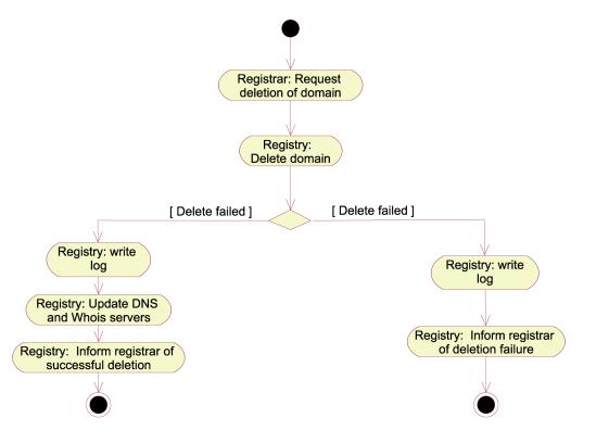
Figure 7:Activity diagram realizing the
"DeleteDomain" use case, activity view
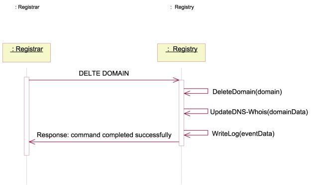
Figure 8:Sequence diagram realizing the "
DeleteDomain " use case, control view
TransferDomain
A domain may be transferred between two RegistrarClients. This may only happen if the Client owning the domain gives the new RegistrarClient permission to take over the domain in question, or in the case of UDRP arbitration or otherwise conflict handling/arbitration by the Registry. Safe transfers are ensured by assigning each domain a transfer password which only the Client owning the domain and the RegistrarClient administrating the domain know. When the Client wishes to move the domain to an other RegistrarClient(B), he informs the new RegistrarClient(B) of his transfer-password. The transfer-password may be requested to be sent to the contact details of the Client as registered in the WHOIS. The Registry will send out this information upon request. RegistrarClient(B) may then use this password to access the domain and issue a transfer request. The typical activities involved in this process are visualized in figure 9. Figure 10 gives a high-level description of the control-flow when transferring domains.
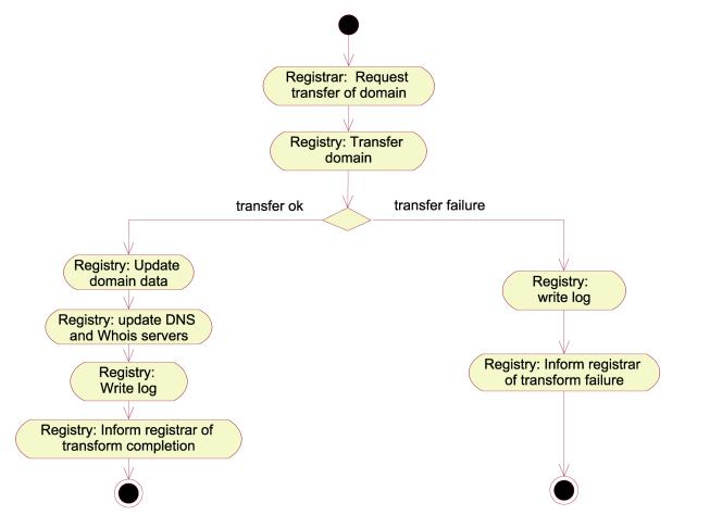
Figure 9:Activity diagram realizing the
"TransferDomain" use case, activity view
.
Figure 10:Sequence diagram realizing the
"TransferDomain " use case, control view
AdminBlockedDomains
The Registry maintains a list of domain names not allowed for registration, according to the Registry policy and current rules. Registrars are not allowed to register domain names that are included in this list. Only the Registry may edit this list.
ApplyForDomain
This use case is an abstraction of the process a Client undertakes when applying for a domain. This process is further refined in the following use case diagram:
Figure 11:Detailed view of "ApplyForDomain " use case (from figure 1 - main use case diagram
The Client (and RegistryClient) may use the WHOIS service provided by the Registry to check if a domain name is taken or not. The only way a client may apply for a domain is through a RegistrarClient. The only situation a Client will be in direct contact with a Registry is in case of domain name dispute (see use case Complaint).
Figure 12:Sequence diagram realizing the “ApplyForDomain" use case, control view
Billing
The prime principle of registrations is that the domain name registrations are prepaid, either in the form of a credit limit, or an actual prepayment of a certain size. This can be combined with an insurance bond from the Registrar, like today’s 100,000 USD requested of the ICANN Accredited Registrars.
The billing and collection systems need not be complicated since the Registry’s billing relations are with the Registrars alone.
Billing process for domain name registration:
· Request registration (Password acknowledged)
· Credit check in database
· Insert domain name
· Acknowledge registration
When a registration is completed, the Registrar’s account balance is debited with the price for one registration. Registrations continue as long as the balance is positive, or until a credit limit, if any, is exceeded.
Once a month, the Registrar is billed with the amount necessary to restore their credit balance. This amount can be chosen by the Registrar himself and can vary from month to month.
Billing at the end of the month:
· Accountant generates a list of all Registrars, with the number of domain names registered during the corresponding month. For each Registrar, a list of every domain registered for this billing period will be included.
· The data goes into the billing system delivered from SAGE, and invoices are generated, printed out and sent by email.
The Registrar can access the billing information and account status through the secure WWW interface, and request the information needed. The support team, key account manager and accountants are also available as telephone support for this purpose, should extra information be needed.
RegistrarAccountAdmin
This use case involves all administration of the individual RegistrarClient accounts. Standard operations as shown in figure 13 are supported.
Figure 13:Detailed view of "RegistrarAccountAdmin" use case (from figure 1 - main use case diagram
Only ICANN accredited RegistrarClients may be given an account. The basic policy of the Registry will be to foster the expansion of the personal domain market through a network of ICANN accredited Registrars. All existing ICANN accredited Registrars will be invited to also become .NAME Registrars. There will be no restriction to the number of Registrars.
Registrars will have a running relationship to the
Registry mostly for billing and credit purposes. Credit for registrations can
be updated at any time.
Reporting
It can be anticipated that the Registry will have a reporting responsibility to entities other than ICANN. These relationships will develop over time.
Complaints
Complaints may
arise either from denial of registration, as would be the case in the event where
a Registrant tries to register a prohibited string. Conflicts and complaints
may also come up as disputes between Registrants.
The Registry will not perform arbitration of disputes. UDRP disputes and other arbitration between Registrants in general will be handled by a third party, e.g. WIPO.
Backup
Backup are taken on a periodically basis and transported offsite by a security company.
Escrow
Approximately once a month a copy of the whole database handling domains and RegistrarClients will be sent to secure storage place offsite. The data will be sent over the Internet, encrypted with an asymmetric RSA encryption algorithm. The keys will be changed at regular intervals. Only ICANN and the Registry may access these copies.
DNSUpdate
The DNS servers will all be continuously updated from the Update Server, which is running as stealth primary DNS. We aim to use BIND9, developed by ISC, which will support the DNS extensions necessary to allow Incremental Zone Transfers (IXFR). Our update server will run a stealth primary DNS server, which will be dedicated to doing updates to our DNS servers with the AXFR and/or IXFR mechanisms of DNS. This server will not be visible to the rest of the world, and it will be connected to our external DNS servers with hardware encrypted VPN cards, to the internal DNS servers using the internal network. This is to ensure that the data arrives at the intended destination without tampering or sniffing on the way. TSIG will also be employed to verify that the data transmitted comes from the correct source and arrives at the correct destination.
Whoisupdate
All the internal and offsite WHOIS servers will run an update server application that will only be accessible from the internal network (separate network cards) in the case of the servers located in the main datacenter, and only through the hardware encrypted VPN cards in the case of the external WHOIS servers. This server application will nonetheless be made as simple and secure as possible. The chroot() system call will be used to restrict the application to a directory, so hackers will not be able to gain access to the system configuration if they get in. The server application will run as a user with low permissions.
To update information on the WHOIS server, client software on the update server will connect to the update server application on the WHOIS server. A typical transfer will look like this:
set alexander.smith.name\n
Domain Name: alexander.smith.name\n
Registrar: The Internet Registrar Company Inc.\n
Registrar Whois: whois.intreg.com\n
Registrar
URL: www.intreg.com\n
Nameserver: ns1.dnshost.com\n
Nameserver: ns2.dnshost.com\n
Modified: 2001-02-17\n
.\n
The update server application on the WHOIS server will read this information, and when it receives a single line consisting of a period only, it will return a confirmation to the client and immediately disconnect.
The first line received will specify what to do and the name of the domain. Two (2) commands will be allowed, “set” and “delete”. If the command is “set”, the update server application on the WHOIS server will read the complete information on the next lines. With the directory hierarchy structure proposed above, the application will know where to place the file containing the information. If the command is “delete”, the WHOIS information for this domain will be deleted.
While the information is being received, it is written to a temporary file on the same filesystem as the resulting file will be placed on. When the transfer is completed, this temporary file will be renamed to the correct name, in this case name/smith/alexander. This will ensure that partial files will never be sent if someone queries a domain while it is being updated, regardless of whether it is the first time the WHOIS information exists for this domain or whether the information is being updated.
This continuous update scheme ensures that the WHOIS data is as “updated” as possible, and that there will be no substantial queues of updates waiting on the update machine. This allows controlled updates even during high-traffic periods and the sunrise period and it also ensures that there will be no massive volume of updates waiting at any time.
The only exception to this would be if the update machine goes down, in which case it would rapidly be replaced with a spare machine in stock, and booted from the ESS, thus getting access to the same data as it had at the time it went down.
Deployment diagrams and system realization
In order to give a good understanding on how the system is to be deployed, we here give a short explanation of the main issues about the hardware structure. Each deployment diagram refers to a package in the package diagram. The diagrams consist of three main elements: nodes, processes and interfaces.
Figure 14:Package diagram of the system components
Registrar client component
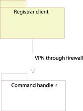
Figure 15: Registrar client component
Figure 16: Deployment diagram of the Registrar client component
The Registrar software communicates via VPN through a firewall. Depending on which protocol the Registrar wishes to use, he chooses to connect to either the RRP or SRRP interface. The software on the client will be open sourced, and the clients may therefore create their own software if they wish to support some special needs.
Security
The Registrars and the Registry communicate with hardware encrypted VPN cards, to prevent eavesdropping and tampering by third parties. Each command from the Registrars has to contain the Registrar’s password, which is verified by the Registry before any command is executed.
Recovery
In the event that an SRRP server has a system outage, there are others in the high availability active/active system configuration that can take over from it. If a RRP-SRRP gateway has a system outage, it can be replaced quickly. There can be several RRP-SRRP gateways, which will be addressed by the same name in the DNS, and will be connected to in a round robin fashion. These gateways will have standard configurations and can be easily replaced.
Scalability:
The high availability active/active system configuration
allows for quick and easy expansion of the number of SRRP servers that handle
requests, transparently to the Registrars. RRP-SRRP gateways can be added by
adding their IP address to the DNS name, also transparently to the Registrars.
Command handler component
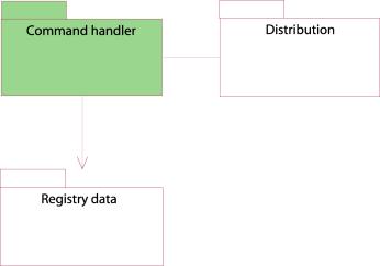
Figure 17: Command handler component
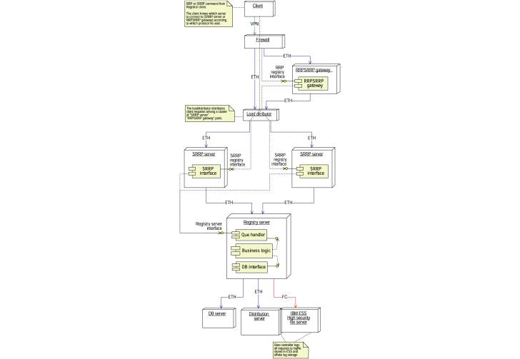
Figure 18:Deployment diagram of the command handler component
The command handler component consists of three elements:
· RRP-SRRP gateway
· SRRP server
· Registry server
The Registry is divided further into the following components:
· Queue handler
· Business logic
· Database interface
The SRRP server receives and queues connections from the Registrar clients. The connections will be held until the command has been processed. If the client uses the RRP protocol, he must connect to the RRP-SRRP gateway. The ERRP server will be able to buffer client connections to handle traffic peaks. The capacity of the front end of the system can easily be enlarged to handle increased load.
The Registry server is responsible for serving the client requests. Internally it is divided into three components:
· The Queue handler will queue commands issued by the SRRP server according to Registrar-id – one queue for each Registrar. The queue will be served in a round robin fashion. The Queue handler will not send more commands to the business logic than the business logic can handle.
· The business logic’s responsibility is to translate the commands into a database statement, and perform other necessary operations before the SQL commands are sent to the database interface.
· The database interface provides an interface towards the business logic that hides the complexity of the database calls. Therefore, the business logic does not see how many databases there are, but only whether the transaction is completed or not. This process runs a double answer protocol: each transaction is run on both databases, and the database interface controls that both databases give the same answer. In case of different database responses, the system stops the registration of database changes, as an error has been discovered.
Security
The firewall prevents hacking into and tampering with data in the system, and changing of system configurations. The VPN cards prevent eavesdropping and tampering with data between the client and the firewall.
Recovery
The SRRP servers are easily replaced with new computers with the same configuration in case of a fatal error. The same applies to the RRP-SRRP gateways.
Scalability
The high availability active/active system configuration allows for quick and easy expansion of the number of SRRP servers that handle requests, transparently to the Registrars. RRP-SRRP gateways can be added by adding their IP address to the DNS name, also transparent to the Registrars.
Another Registry server can be added to the system,
connecting each to half of the SRRP servers. More Registry servers can be added
in the same way. The databases can be scaled by using parallel systems.
Distribution
component
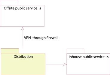
Figure 19: Distribution component
Figure 20:Deployment diagram of the distribution component
The distribution component’s responsibilities are to distribute the changes that have taken place to the local as well as the offsite DNS and WHOIS services. The command handler communicates the changes in the database that have been successfully completed to the distribution component. Here, the update daemon receives the changes. It processes the data and produces an update message to the WHOIS and zonefile. The changes are therefore reflected to the WHOIS and DNS servers immediately. The distribution server will be set up as a primary stealth server to accomplish the DNS updates.
The offsite WHOIS /DNS servers are connected to the system by VPN channels in order to maintain a secure transmission of WHOIS and zone file updates.
Security
Security is assured by the use of a firewall and dedicated VPN cards.
Hardware failure strategy
Since the distribution server is booted from the ESS, it is easy to replace the distribution server. Backup hardware will always be maintained to take over in case of fatal hardware errors on the distribution server.
Scalability
The distribution server can be split into separate WHOIS and DNS update machines, and in addition, can be split into machines dedicated for updating groups of WHOIS and DNS servers.
Registry
data
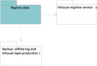
Figure 21: Registry data component
Figure 22: Deployment diagram of the registry Registry data component
The command handler’s database interface communicates with the two mirrored databases through their SQL interfaces. Each database is connected to the ESS, which provides secure data storage. Both DB servers are stored on separate disks in the ESS, which is also internally mirrored.
The Registry data is periodically sent to the Escrow agent which will hold them in escrow according to the agreement.
Security
This is purely an in-house system, and will not be accessible to others.
Recovery
Hardware failure strategy:
If one of the two databases stops, the remaining database will still serve the read requests from the inhouse public services and the billing system, but changes in the data cannot be made until both databases are running. In case of a total breakdown of both databases, the backup tapes or the offsite log will be used to recreate the database. Extra hardware will always be ready to replace a broken unit.
Scalability:
Parallel versions of the databases can be installed. The ESS is scalable. The Registry server is scalable, as explained above.
Billing
component
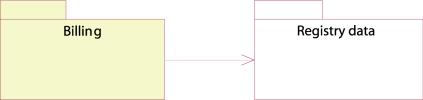
Figure 23: Billing component
Figure 24:Deployment diagram of the registry Registry data component
The billing component is a simple database system that reads and edits Registrar data from the tables. The only access this database has to the system is to read and edit information relevant to the billing task.
Security:
This is purely an in-house system, and will not be accessible to others.
Recovery:
Hardware failure strategy:
Since the database can easily be installed on another computer, it is easy to replace the node on which the billing system resides. Since the data are stored on the ESS, the entire database system has to break down before the billing system will be affected.
Scalability:
Billing is a manual job run once a month, and does not need capacities for scaling beyond that of the database, which is described above.
Backup
component
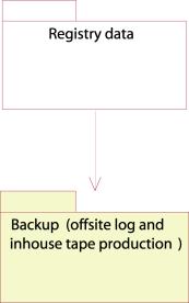
Figure 25: Backup component
Figure 26:Deployment diagram of the Registry data component.
.
The backup component consists of both offsite log writing and backup tape producing. The log will be written through the distribution server to an offsite log storage. The log messages are encrypted and transmitted through a VPN channel from the distribution server to the log storage.
The backups are controlled from the backup controller, where a daemon controls the periodically production of backup tapes.
Security
The backup is secured with a firewall and VPN so that data is not compromised, hacking is prevented.
Recovery
Hardware failure strategy
New tapes can be easily acquired and a new backup robot will be acquired as part of the service level agreement with the supplier.
Scalability
Additional backup solutions can be added in case of high volume.
In-house
public services:
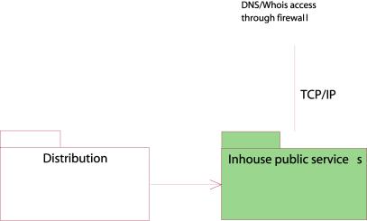
Figure 27: In-house Public services
Figure 28:Deployment diagram of the in-house public services component
The in-house public services offer the outside world a DNS and WHOIS service. The service consists of a high-availability active/active configuration, which can easily be expanded. The load distributor spreads the load onto the different DNS/WHOIS servers.
The distribution server transmits new zone files and WHOIS information immediately when the change is received from the command handler. The distribution server also contains complete WHOIS and zone file so that associated DNS’s and WHOIS servers can be restored completely from the distribution server.
Security
The firewall secures the in-house public services from hacking.
Recovery
Hardware failure strategy:
The high availability active/active configuration makes it easy to maintain the service in a hardware failure situation. The distribution server can be easily replaced in case of a hardware failure, allowing for updates again.
Scalability
The high availability active/active configuration allows for easy scalability by adding more components.
Offsite
public services
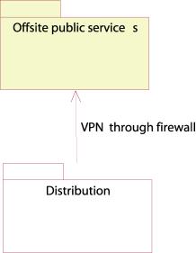
Figure 29: Offsite public services
Figure 30: Deployment diagram of the offsite public services component
.
The distribution server also passes changes immediately to the offsite DNS/WHOIS servers through a VPN channel.
Security
Security is assured with the VPN cards and the firewall,
so tampering and eavesdropping do not occur.
Recovery
Hardware failure strategy:
Since there exists multiple offsite DNS and WHOIS servers, these services will always be provided from at least one of them.
Scalability
More DNS and WHOIS servers can be installed at different locations in case of high load.
In-house
registrar service component
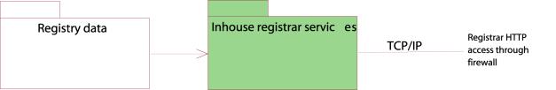
Figure 31: In-house registrar service component
Figure 32: Deployment diagram of the in-house registrar Registrar service component
This is the Registrar’s web interface towards the system. The load distributor is equipped with a high availability active/active system, which detects if one of the web servers is down, and redirects the requests to the operating web server(s). The web servers are connected to one of the databases, but switches database connection if the database goes down. Since the system is configured in an active/active fashion, the capacity may be expanded by adding new nodes.
Security
Security is assured with the VPN cards and the firewall,
so tampering and eavesdropping do not occur.
Recovery
Hardware failure strategy
The high availability active/active configuration makes it easy to maintain the service in a hardware failure situation.
Scalability:
The high availability active/active configuration allows for easy scalability by adding more components.
Physical diagrams and structures
Hardware
The following diagram describes the physical structure of the main data center:

Figure 33: Hardware deployment in the main data centre
The Registry has three connections to the Internet, which mainly consist of the following:
1) Secure entry point for Accredited Registrars to register domain names and other operations in the database
2) Interface to the Internet for DNS servers, WHOIS servers and WWW servers
3) Connection to external data centers where secondary DNS servers, supplementary WHOIS servers and log machines are hosted
General information about the hardware
Most of the servers in the main data center are diskless and have disks as a partition on the Enterprise Storage System (ESS). The ESS is a internally mirrored, RAID controlled system which allows all machines to boot directly from it, instead of from a local disk. The great advantage of this is that once a server fails and has to be replaced, it will need no swapping of disks or installations, and can boot directly from the ESS with minimal total downtime.
There will be a stock of pre-configured servers (set up to boot from the ESS) as an immediate replacement for critical servers that fail. The Incident Response Team will change any failed server with one from the stock.
All servers are connected to an operator terminal so all servers can be accessed.
Entry point for Accredited Registrars
The entry point for the Accredited Registrars is on the left side of the above figure, where connection is ensured through the PIX firewall. The Registry wants to encourage the use of a secure channel for all transactions to the database through an encrypted Ipsec VPN channel. The use of such hardware, however, is not mandatory, and the Registrars willing to accept a lower level of security for their interface may use the software options available such as SSL. It is believed that it would be advantageous for all parties to have a higher security on the transactions, since it involves billing, updates to the database and other critical operations. The Registry will provide information compliant hardware to ensure encrypted communication with the ICSA compliant Ipsec VPN cards installed both by the Registrars and the Registry.
The Registrars have two alternative connection points behind the PIX, the RRP server or the SRRP server. The first is running the RRP protocol as defined in RFC2832, the second (SRRP), a state-less protocol which is designed and proposed by the Registry as an alternative to the established RRP, to provide faster registrations and easier implementation for new registrars than what is provided through RFC2832 RRP.
The SRRP servers are running in an high availability active-active system, while the RRP server translates the RRP protocol requests to the SRRP protocol which are sent to the servers. We encourage the Registrars to use the SRRP because of its simplicity and speed.
WWW entry point
The general entry point for Internet users to the DNS servers, the WHOIS servers and the WWW servers of the Registry is located in the middle of the above figure. This entry is unencrypted except for SSL, the PIX firewall will provide standard protection for this commonly accessible interface.
The DNS servers, the WHOIS servers and the WWW servers are set up in a active-active system, controlled by the local director. It is extremely scalable and new servers can be added to any side of the solution to scale for higher load.
External data-centers for DNS and WHOIS
The connection to the external data-centers, some of which are put on different backbones, is located in the right part of the hardware diagram above. The external data-centres are connected to the main data center through a VPN hardware encrypted network, through which updates to the DNS and WHOIS servers are done. The number of external DNS and WHOIS servers is extremely scalable, and new centers can be added if needed. The external WHOIS servers will take load off the internal WHOIS servers in high-traffic periods, and all DNS and WHOIS servers will be updated continuously.
Software structure
The following figure is meant as a high-level summary of the software that is running in the Registry.
Figure 34: Software high level structure
Database description and structure
Figure 35: Database ER diagram
Table Descriptions
Domains
This
table contains all information about the single domains, such as when it
expires, what nameserver-cluster it uses, and what it’s status is. All columns
must be NOT NULL.
SLD
This
table is made to allow distribution of nameservers for domains on the second
level. When the Registry only allows registrations on third level domains, it
is possible to register many more domains than is possible on second level
domains, and when there are a lot of domains registered, this may be necessary.
Also, the introduction of IPv6 will make DNS a much more complex application,
which will again necessitate load distribution. In the beginning, we will for
example start distributing all domains starting with a-m on the second level to
one nameserver cluster and the rest, n-z, on another nameserver cluster. In the
beginning it is not necessary to use this table. All columns must be NOT NULL.
Clusters
The
clusters table contains all the cluster-IDs and the respective nameservers. At
least 2 nameservers must be in a cluster for it to be valid. All columns must
be NOT NULL.
Registrar
This
table contains all the Registrar information needed in the database, including
billing information and the Registrar password. All columns must be NOT NULL.
Cluster_Nameservers
This
table contains all the clusterids with all the belonging domain names and IP
addresses. All columns must be NOT NULL.
Blocked
The
Blocked table contains all the words that are blocked on second and third level
domains. All columns must be NOT NULL.
Blocked_combo
This
table contains all the combinations of third level and second level domains
that are blocked. All columns must be NOT NULL.
Location, connectivity and environment descriptions
Physical Security
A physical security system to prevent unauthorised person(s) from obtaining physical access to the premises or the equipment on site should be in place. As a minimum this should consist of access control equipment, intrusion detection equipment and CCTV surveillance equipment as well as having 24-hour security staff on the premises. It should provide access for authorised personnel 24 hours a day.
Hosting Space
Hosting space is to be available within cages and should provide for either standard 19” racks or to allow the installation of non-standard sized equipment, floor mounted equipment or special/custom racks. The cage space should be flexible in that if required, cages can be joined together to form larger caged areas.
Electrical Power
Each full rack or cabinet is to be provided with 10 Amps, 220-240 Volt AC electrical power, on dual redundant power strips.
Electrical power is to be supplied to the co-location centre through two independent circuits from the local power company. The supply must be conditioned and supported by UPS systems and backup diesel generators. All power systems should be designed with N+1 redundancy to ensure reliable operation.
Air Conditioning
Air conditioning is to be provided in the co-location centre with N+1 redundancy and be capable of maintaining the environmental temperature at 20°C ± 5°C and humidity between 20% and 65% suitable for server equipment.
Environmental Monitoring
The physical environment is monitored 24 hours a day. These systems check a full range of environmental factors including, temperature, humidity, power, security systems, water detection etc. If any system is found to be operating outside normal working parameters, the on-site staff will investigate and arrange for the appropriate service or maintenance work to be carried out.
Fire Suppression
A fully automatic fire detection and alarm system that is linked to automatic suppression systems is required, with the suppression system based on Argonite (or similar).
Facilities
It would be preferred if within the location there are meeting room spaces available. Additionally, there should be available a loading and staging area where equipment deliveries can be accepted 24 hrs a day into a secure area.
Burstable
Bandwidth
The available bandwidth should provide for a dedicated 100Mbps burstable bandwidth on a dedicated Ethernet port direct to the cage area via redundant network connections.
The bandwidth should be billed based on utilisation. Internet connectivity is to be guaranteed with a robust Service Level Agreement for network availability and performance.
Facility Staff
On-site technical staff should be able to provide the following services on a 24x7x365 basis
· Server rebooting or power cycling
· Visual inspection
· Carrying out basic commands, given detailed instructions
· Installing equipment into racks
· Cable patching
· Changing tapes or other removable media
Server & Network Monitoring
All servers and network equipment should be externally monitored automatically, by polling the hardware interface of each component, sufficient to identify within a maximum of five minutes when a problem occurs.
Notification
In the event that a condition requiring notification occurs, then this must be possible through email, telephone, pager as well as other means.
Bandwidth Reports
Utilisation reports on the level of bandwidth used should be available on a regular basis, at least monthly, with interim reports if required. These should be capable of providing further substantial detail if required.
Administration
Telephone
support must be available 24 hours a day, supported by a fully integrated problem
management process to identify and track problems.
Technical Engineering Support
Skilled hosting engineers, network engineers and onsite operations support should be available ona 24x7x365 basis.
Service Level Guarantee
Routine and Scheduled Maintenance
No interruption for routine or scheduled maintenance is acceptable, nor would any activity that would result in the facility operating in an unprotected mode.
IBM will be looking at how the hosting of the Registry can be done and how it can be subcontracted out.
D15.2.2 Registry-Registrar Protocol and interface
Interface to the Registry
The configuration of the system for registrations is designed to give the Registrars a problem free, secure and fair access to registrations.
· The firewall and the VPN cards guarantee security, allowing the Registry and the Registrar to perform transactions with greatly reduced risk of sensitive data being compromised.
· The load balancer allows the traffic to be equally distributed over several hardware components, reducing the risk of downtime caused by hardware or software failure in the Registry servers. Also, the capacity for registrations can be increased. If there is a traffic peak that is higher than the Registry can handle in real time, this traffic can be buffered in the Registry servers until the database is available, given that the peak is not so high that all the Registry servers are overloaded. If this is the case, more Registry servers can easily be added.
· Transactions from the Registry servers are passed along and queued on the Registry Logic Unit (RLU) in a controlled manner, making sure that the RLU is never overloaded. The RLU queues the transactions with one queue per Registrar. The transactions will be chosen from each queue in a round robin fashion, skipping empty queues. This allows for a fair distribution of transactions from each Registrar under periods of high load.
A new, Stateless
Registry-Registrar Protocol
GNR is
proposing a new protocol for the communication between the Registry and the
multiple Registrars. This new protocol, called the Stateless Registry-Registrar
Protocol, or SRRP, is designed to overcome most of the known problems with the
existing RRP in use today, as defined in RFC 2832. The SRRP is suggested as a
supplement to the RRP and the Registry will encourage the Registrars to use
this protocol for communications with the Registry, although a supplementary
interface will exist for the Registrars to use their existing RRP
implementations.
The
protocol suggested herein will in the case of delegation from ICANN be
submitted as a new RFC, as in Appendix D.5.
In order
to promote usage of SRRP, the Registry will provide the Registrars with APIs to
the protocol to make it easy and fast to implement. Given its stateless nature,
it is easier to implement for new Registrars than the RRP, and have advantages
also in other areas:
· Transfer commands may be approved by the Registrant through the domain password, and domain transactions may be performed without approval from the Registrar, from which the domain is being transferred .
· The protocol uses coordinated universal time (UTC) for all operations.
· The client may discover system defined default values and limits
· The protocol provides the client with complete idem potency, and repeated commands will not alter data additionally.
· It puts less strain on the server by using a stateless protocol model and moving some of the complexity to the clients.
· The protocol is designed to minimize the number of database transactions in order to keep the performance high.
GNR will
in the case of delegation submit the protocol for review as a RFC (attached).
Abstract of the protocol
The
purpose of SRRP is to provide a stateless service for communications between
the Registrar and the Registry. The design goal of the protocol is to provide a
consistent service for a very large number of clients by not maintaining client
state information on the server, and to reduce the policy enforcements done by
the protocol to a minimum.
The
protocol describes the communications between a Registrar, normally acting on
behalf of a Registrant, and the Registry. The Registrar may perform operations
such as creating domains, creating logical entities of name servers, assigning
name servers to a domain, transferring a domain and querying the server for
information about name server entities, domains or the server itself.
The SRR
protocol is intended to fix several shortcomings of the RRP defined by NSI in
RFC2832 by removing some of the less frequently used features and using a
stateless protocol model. The goals of the protocol are:
·
Provide
only the strictly required functionality
·
Provide
a completely stateless service
·
Provide
service to a very large number of clients
·
Be
implementation and performance friendly
Terminology used
·
The
“request message” or “client request” is the message sent from the client to
the server, and consists of a one line “request header” and a multi line
“request body”.
·
The
“response message” or “server response” is always the response to a request
message, and is sent from the server to the client. It consists of a one line
“response header” and possibly a “response body”.
·
“LWS”,
linear white space, is any combination of ASCII space (SP) and ASCII tabulator
(TAB) characters.
·
“CRLF”
is one ASCII carriage return (CR) character followed by one ASCII line feed
(LF) character.
·
An
“attribute/value pair” consists of a short textual string, termed “attribute”,
an ASCII ‘=’ character, and another string, termed “value”. The attribute/value pair is terminated by a
CRLF sequence, and thus a line may only contain one attribute/value pair.
·
The
“client” is the Registrar’s client software, and likewise the “server” is the
Registry’s server software.
·
An
“object” is a set of attribute/value pairs that the server operates on.
Currently there are two kinds of objects: domain objects and cluster objects.
The key
words “MUST”, “MUST NOT”, “REQUIRED”, “SHALL”, “SHALL NOT”, “SHOULD”, “SHOULD
NOT”, “RECOMMENDED”, “MAY”, and
“OPTIONAL” in this document are to be interpreted as described in RFC 2119 [1].
Protocol model
The
protocol is a simple one way client-server protocol using a textual format for
easier debugging. A transaction is always initiated by the client, and the
server must answer every valid request message with a response message
containing a response code indicating the outcome of the client request. A well
behaved client SHOULD wait for a response from the server before it issues a
new request.
The
messages should contain only printable ISO-8859-1 characters, ie. characters in the range 31-126 and 160-255,
inclusive. Support for other characters sets or binary data are not supported
in the current version of SRRP, but may be added later by using a character
encoding.
The
Registrar is identified to the Registry by an attribute/value pair in the
request body, and authenticated by a similar attribute/value pair. As the protocol does not itself provide any
other security measures, the client MUST connect to the server using a secure,
reliable communication method such as SSL [2] or an encrypted tunnel.
Protocol
objects
The
domain objects are a logical grouping of attribute/value pairs that are
manipulated using SRRP.
Domain objects
The
domain object is a collection of information defining a registered domain in
the system. The domain object should contain the following attributes:
·
Exactly
one “registrar-id” attribute identifying the owner of the object.
·
Exactly
one “domain-name” attribute containing the name of the domain.
·
Exactly
one “expiry-date” attribute containing the expiry date for the registration. If
the client does not specify a date, a system default should be used.
·
Exactly
one “status” attribute defining the current status of the object.
·
This
should be set to a system default if not specified by the client.
·
Exactly
one “expiry-date” attribute containing the expiry date for the registration. If
the client does not specify a date, a system default should be used.
·
Exactly
one “cluster-id” attribute identifying a cluster object for this domain object.
Cluster objects
The
purpose of the cluster object is for the Registrar to create a single object to
which the Registrar can attach domain names, thereby facilitating the handling
of large volumes of domain names using the Registrar’s DNS servers.
The
cluster object is a collection of name server information. Both the name and
the address of the name server are stored for every name server in the cluster.
The name servers are stored in attributes starting with “nsi-“ where “i” is any
positive integer starting with one (1), possibly limited by the server. For
instance, the first name server in a cluster object will have its IP address in
the attribute “ns1-address” and its name in the attribute “ns1-name”. This pair
is termed the “name server entry”.
The
client should store the name servers in increments of one, as the server MAY
choose to stop looking for name servers when it finds an empty name server
entry, thereby assuming that the name server cluster is full.
The
cluster object consists of any number of name server entries starting with
“nsi-“ where i is a positive integer starting with one (1) and increasing with
increments of one (1) for every name server entry.
Request
message format
The
issued request message consists of a header line containing the command to be
performed, a command argument and the version number of the protocol. These
fields are separated by one or more LWS characters, and the header line is
terminated by one CRLF character sequence.
Following
the header line, the client may add one or more lines of attribute/value pairs,
the request body. While the protocol does not require the client to issue any
attribute/value pairs, the authentication credentials are specified using
attribute/value pairs in the request body, and these are required by every
command currently specified. The order of the attribute/value pairs in the
request body is arbitrary.
The
request message is terminated by the ASCII end of file (EOF) character, and the
server MUST disconnect from the client whenever it encounters EOF.
Example
request message:
CREATE DOMAIN SRRP/1.0
registrar-id=123456789
registrar-auth= pass-phrase
domain-name=example.com
status=inactive
cluster-id=987654321
Please
note the usage of ‘=’ and space characters in the registrar-auth attribute
value. This is valid because there must be exactly one attribute/value pair on
every line, and everything from the first ‘=’ up to the CRLF is considered part
of the attribute value.
Response
format
For
every valid request message received from a client, the server MUST issue a
response message starting with a one line header containing a valid response
code and a short description of the response code, separated by one or more LWS
characters and terminated by a CRLF sequence.
If the
client request was completed successfully and the server needs to send
additional information in the response message, it must send this information
in one or more lines of attribute/value pairs contained in the response body.
The response body is terminated by an EOF character, also marking the end of
the response message. If the command failed, the response code is a 3XX
(Temporary failure) or 4XX (Permanent failure), the server MAY add one or more
“text” attributes in the response body further describing the error condition.
The
response body for a successful command MUST contain only attributes defined for
that particular command. The order of the attributes in the response body is
arbitrary with one exception: the order of the special “text” attribute is
important as these are used for human readable data. The server MUST send the “text” attributes in the order they are
stored or retrieved, and likewise the client MUST read them in the order
received.
Example
response message for a QUERY CLUSTER command:
200 Command completed successfully
ns1-address=192.168.4.5
ns1-name=ns1.example.com
ns2-address=192.168.4.6
ns2-name=ns2.example.com
ns3-address=10.10.56.11
ns3-name=ns1.example.net
The
response code of 200 indicates that the command was successfully completed, and
the response body contains the data returned from the command, which is a set
of attribute/value pairs.
Example
response message for a QUERY DOMAIN command:
200 Command completed successfully
domain-name=example.com
registrar-id=123456789
expiry-date=2003-02-09
created-date=2001-02-09
cluster-id=987654321
status=active
text=Last-change: CREATE DOMAIN
text=Changed-date:2001-02-13 10:15:12 UTC
text=Changed-by: registrar 123456789
This is
a more complex response, containing both normal attributes and ordered “text”
attributes. If the domain did not exist, the response would be a 401 Domain not
registered, possibly with one or more “text” attributes giving a human readable
explanation of the error.
Client
requirements
The
client MUST NOT make any assumptions about the length of the value pairs. The
ordering of the attributes is irrelevant except for the “text” attribute where
the client MUST keep the order.
Server
requirements
The
server SHOULD issue a response message to every well formed client request
message. A client request message is considered well formed when it contains an
initial header line consisting of three fields separated by one or more LWS
characters, and the last value is recognized as an SRRP protocol version
number. If the client request message is not well formed, the server MUST drop
the connection immediately.
The
server MUST answer the client request with a response message using the same
version of SRRP as the client request message. If the server is unable to answer
the request using the same protocol version as the client, it must issue a 413
Unsupported protocol version message.
SRRP commands
This
section contains the commands defined for use in client request messages and
their expected response. All of these messages MUST contain a “registrar-id”
attribute identifying the Registrar issuing the command, and a “registrar-auth”
authenticating the Registrar. Clients may only view and/or change their own
objects, and attempts to operate objects belonging to other Registrars should
result in a 411 Access denied error message.
Note
that the ordering of the attribute/value pairs is not significant except for
the “text” attributes.
CREATE
The
create commands are used for adding an object to the Registry. In the current release
of SRRP, the “domain” and “cluster” object types are supported, containing a
domain registration and a series of name server registrations, respectively.
CREATE DOMAIN
The
CREATE DOMAIN command attempts to register the domain name contained in the
“domain-name” attribute in the request body.
The
request body MAY also contain any of the following attributes:
·
Exactly
one “expiry-date” attribute giving the requested expiration date of the
registration..
·
Exactly
one “cluster-id” attribute pointing to a cluster object containing the name
servers for this domain..
·
Exactly
one “status” attribute giving the current status of the domain.
·
Exactly
one "domain-auth" attribute containing a Registrar assigned password for this domain.
·
Zero
or more (possibly server limited) name server entries each consisting of the
attributes “nsi-address” and “nsi-name” where “i” is a positive integer.
If the
user specifies any name server entries, the server must attempt to create a
cluster object for these. If successful, it MUST return the following
attribute/value pairs:
·
Exactly
one “cluster-id” attribute containing the cluster ID of the newly created
cluster object. The client must store this value as it is the only way of
keeping track of the cluster object.
·
Exactly
one “expiry-date” attribute containing the expire date for the domain.
·
Exactly
one “status” attribute containing the status of the domain.
Note
that the server may limit the minimum and/or maximum number of nameservers the
user is allowed to specify. The server should notify the client of any
limitations on the number of name servers in the STATUS DEFAULTS response body.
If the
client specifies both a “cluster-id” attribute and any number of name server
entries, the server SHOULD ignore the name server entries and use the cluster
ID.
If the
cluster ID does not exist in the system, the response message should be a 402
Cluster not registered. If the expiry date is invalid, the response message
should be a 405 Invalid expire date. If the “status” attribute contains an
unknown status value, the response message should be a 404 Invalid attribute
value. If the client specified too few or too many name servers, the server
should respond with a 406 Invalid number of name servers error message. If the
client attempts to register a domain which is blacklisted, the server should
issue a 409 Blocked domain error message. If the client does not have the
necessary credit to register a domain, the response message should be a 410
Credit failure error.
Examples:
CREATE DOMAIN SRRP/1.0
registrar-id=123456789
registrar-auth= pass-phrasecluster-id=987654321
domain-name=example.com
In this
example, the Registrar 123456789 adds the domain example.com using the default
expiry date and status and a pre-defined cluster object.
CREATE DOMAIN SRRP/1.0
registrar-id=123456789
registrar-auth=pass-phrase
domain-name=example.com
ns1-address=114.72.91.131
ns1-name=ns1.example.com
ns2-address=114.72.91.132
ns2-name=ns2.example.com
Here,
the Registrar specifies two name servers in the request body. If the number of
name servers (two) is valid, the response might look like this:
200 Command completed successfully
cluster-id=987654321
expiry-date=2004-03-12
status=active
The
client would now own the cluster object identified by 987654321 containing the
two name servers ns1.example.com and ns2.example.com and their IP addresses.
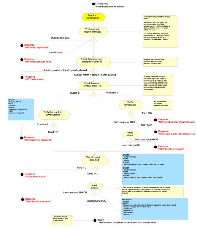
Figure 36: Create Domain
CREATE CLUSTER
Cluster
objects for name servers may be added by using the CREATE CLUSTER command. A
number of name server entries each consisting of the attributes “nsi-address”
and “nsi-name” where “i” is a positive integer. The minimum and/or maximum
number of name server entries may be limited by the server, and the server
should show these limits in the STATUS DEFAULTS response body. The server must
create a cluster object for this client, and respond with a “cluster-id”
attribute in the response body containing the ID of the newly created cluster
object. The client must store the cluster ID as this is the only way of keeping
track of the cluster object.
If the
client specified too few or too many name servers, the server should respond
with a 406 Invalid number of name servers error message.Example:
CREATE CLUSTER SRRP/1.0
registrar-id=123456789
registrar-auth=pass-phrase
ns1-address=114.72.91.131
ns1-name=ns1.example.com
ns2-address=114.72.91.132
ns2-name=ns2.example.com
ns3-address=114.72.91.133
ns3-name=ns3.example.com
A
typical response message would look like this:
200 Command completed successfully
cluster-id=987654321
The
cluster identified by the cluster ID 987654321 is now assigned to the Registrar
identified by the Registrar ID 123456789, and contains three name servers.
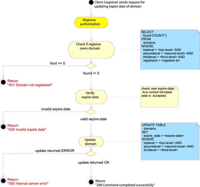
Figure 37: Create cluster
SET
The SET
command is functionally equivalent to the CREATE command, except for that it
will overwrite any previous data contained in the attribute.
SET EXPIRE
If not
specified, the expiry date is set to a system default time, ie. a year after the registration was performed.
However, the Registrar may change the expiry date himself by issuing an SET
EXPIRE command with the domain in the “domain-name” attribute and the requested
expiry date in the “expiry-date” attribute. The previous expiry date of the
domain object will be overwritten by the new one.
The
value of the “expiry-date” attribute should be the year month and day of the
requested registration expiry date, specified with a four digit year number, a
two digit month number and a two digit day number, separated with ASCII ‘-‘
characters. The client MUST specify the expiry date in UTC (Universal Time
Coordinated).
The
system may have an upper limit of the length of a registration, and if the
Registrar attempts to set an expiry date past this boundary, the server must
respond with a 405 Invalid expire date error message.
Example:
SET EXPIRE SRRP/1.0
registrar-id=123456789
registrar-auth=pass-phrase
expiry-date=2007-06-04
domain-name= example.com
This
will set the expire date of the domain example.com to June 2007.

Figure 38: Set expire
SET CLUSTER
The SET
CLUSTER combination will specify a cluster of nameservers, identified by the
“cluster-id” attribute in the request body, for the domain object specified by
the “domain-name” attribute.
If the
domain and/or cluster object is unknown, the server must respond with a 401
Domain not registered error message. If
the cluster object is unknown, the server must respond with a 402 Cluster not
registered error message.
Example:
SET CLUSTER SRRP/1.0
registrar-id=123456789
registrar-auth=pass-phrase
cluster-id=987654321
domain-name=example.com
Here the
client will change the “cluster-id” attribute for the domain example.com to
987654321, if both the domain and cluster objects exist.
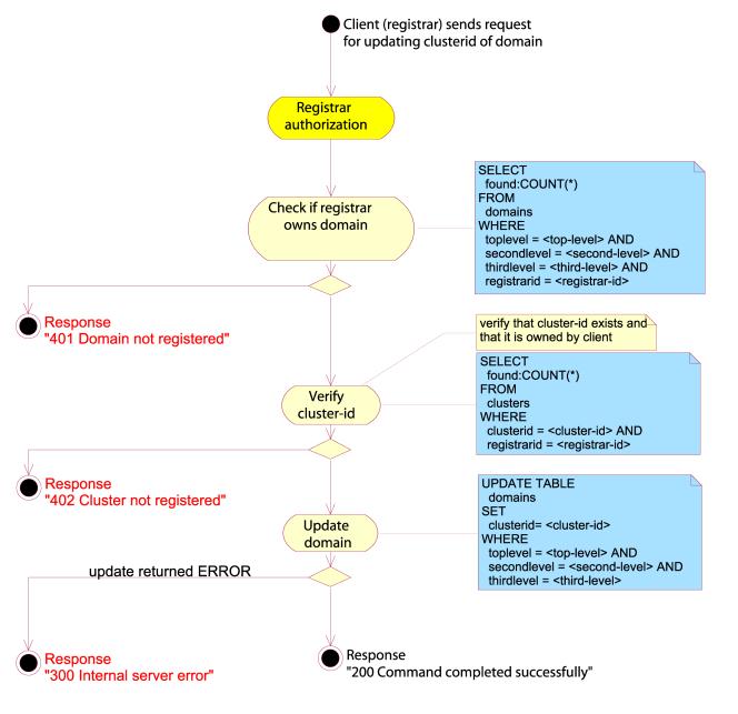
Figure 39: Set cluster
SET STATUS
The
client may change the status of a domain object by using the SET STATUS
command. The following values are valid:
·
“inactive”
signaling that the domain is not active.
·
“active”
signaling that the domain is active.
Example:
SET STATUS SRRP/1.0
registrar-id=123456789
registrar-auth=pass-phrase
domain-name= example.com
status=inactive
In this
example, the client deactivates the domain “example.com” by setting its status
to “inactive”.
i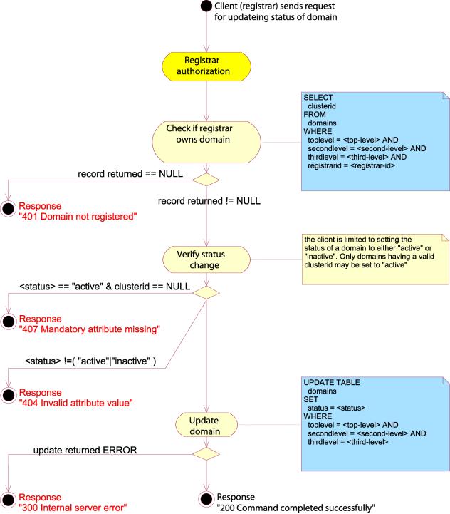
Figure 40: Set status
SET NAMESERVERS
The SET
NAMESERVER command is used for changing all of the name server entries in a
cluster object. The request body should contain exactly one “cluster-id” object
identifying the cluster object and a number of name server entries defining the
new name servers for the cluster object.
The name server entries consist of the attributes “nsi-address” and
“nsi-name” where “i” is a positive integer. The minimum and/or maximum number
of name server entries may be limited by the server, and the server should show
these limits in the STATUS DEFAULTS response body.
The new
name server entries should completely replace all previous name server entries.
If the
cluster ID does not exist in the system, the response message should be a 402
Cluster not registered. If the client specified too few or too many name
servers, the server should respond with a 406 Invalid number of name servers
error message.
Example:
SET NAMESERVERS SRRP/1.0
registrar-id=123456789
registrar-auth=pass-phrase
cluster-id=987654321
ns1-address=171.81.19.159
ns1-name=ns1.example.com
ns2-address=171.81.19.160
ns2-name=ns2.example.com
This
will completely remove any name server entries from the cluster object in
question, and replace them with the two name servers above.
Figure 41: Set nameservers
SET PASSWORD
The
client may change the domain password of a domain object using the SET PASSWORD
command. The new domain password should be given in the "domain-auth"
attribute.
The
purpose of the domain password is to authorize domain transfers between
registrars. The transfer request message should contain the domain password for
the requested domain, and the server should only perform the transfer when the
password is correct. Example:
SET
PASSWORD SRRP/1.0
registrar-id=123456789
registrar-auth=pass-phrase
domain-name=example.com
domain-auth=domain-pass-phrase
domain-pw-set=new-domain-pass-phrase
DELETE
The
DELETE command is used for deleting objects.
DELETE DOMAIN
The
DELETE DOMAIN command will attempt to delete a domain object. The request body
must contain exactly one “domain-name” attribute specifying the domain to be
deleted.
If the
domain object cannot be found, the server must respond with a 401 Domain not
registered error message.
Example:
DELETE DOMAIN SRRP/1.0
registrar-id=123456789
registrar-auth=pass-phrase
domain-name=example.name
This
will delete the domain example.name provided that the Registrar attempting the
operation has the proper authorization.
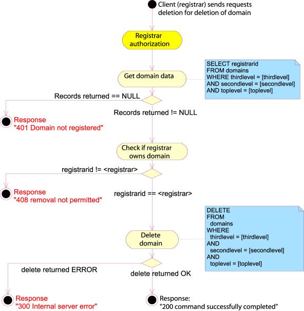
Figure 42: Delete domain
DELETE CLUSTER
The
DELETE CLUSTER command will attempt to delete a cluster object. The request
body must contain exactly one “cluster-id” attribute identifying the cluster
object to be deleted.
If the
cluster object cannot be found, the server must respond with a 402 Cluster not
registered error message. If a client attempts to delete a cluster object,
which is in use by one or more active domain objects, the server should return
a 408 Removal not permitted error message. The client will have to assign
another cluster ID to the domain objects using this cluster object, or set
their status to “inactive” before attempting the operation again.
Note
that all the name server attribute groups contained within the cluster object
will be deleted too.
Example:
DELETE DOMAIN SRRP/1.0
registrar-id=123456789
registrar-auth=pass-phrase
cluster-id=987654321
This
will delete the cluster object identified by the “cluster-id” attribute.
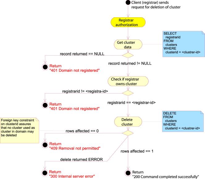
Figure 43: Delete cluster
QUERY
The
QUERY commands are used for fetching all the available information about an
object.
QUERY DOMAIN
The
QUERY DOMAIN command will attempt to retrieve some or all of the information
for a domain. The request message must contain exactly one “domain-name”
attribute giving the name of the domain object to query, and zero or more
“get-specific” attributes naming the specific attributes to fetch.
If no
“get-specific” attributes are present in the query, the server must return all
available information for the domain object. If one or more “get-specific”
attributes are specified, the server must return the values of all the
attributes named by the “get-specific” attributes or an error message.
If the
server is unable to return the required information, it must return a 301 Attribute
temporarily unavailable. If one or more of the “get-specific” attributes
contains an unknown attribute, the server must return a 403 Invalid attribute.
If the client attempts to query a domain which is not registered, the server
must return a 401 Domainnot registered.
Normally
Registrars should only be able to query their own domains, and attempts to
query other Registrars’ domains should result in a 411Access denied error..
If there
are no “get-specific” attributes in the query, the server MUST return at least
the following information:
n
The
current Registrar id in the “registrar-id” attribute.
n
The
domain name in the “domain-name” attribute.
n
The
expiry date in the “expiry-date” attribute.
n
The
current status of the domain in the “status” attribute.
If the
server is unable to retrieve this information, it MUST respond to the client
with a 301 Attribute temporarily unavailable, indicating the failure to
retrieve the required information about the domain.
The
response to a query without any “get-specific” attributes SHOULD also contain
the following information:
n
The
creation date of the domain in the “created-date” attribute.
n
The
cluster ID of the cluster object for this domain in the “cluster-id” attribute,
if set.
n
Any
other relevant information about the domain contained in ordered “text”
attributes.
Example
query retrieving only the “expiry-date” attribute:
QUERY DOMAIN SRRP/1.0
registrar-id=123456789
registrar-auth=pass-phrase
domain-name= example.com
get-specific=expiry-date
This
command should return the “expiry-date” attribute for the domain example.com,
and a successful response might look like this:
200 Command completed successfully
expiry-date=2004-12-20
Example
query retrieving all the available information:
QUERY DOMAIN SRRP/1.0
registrar-id=123456789
registrar-auth=pass-phrase
domain-name= example.com
This
command will try to retrieve all the information for the domain example.com. If
it is successful, the output might look like this:
200 Command completed successfully
domain-name= example.com
registrar-id=123456789
expiry-date=2004-12-20
created-date=2001-01-20
cluster-id=987654321
status=inactive
text=Change: SET STATUS (to inactive)
text=Changed-date:2001-04-03 12:46:01 UTC
text=Changed-by: registrar 123456789
text=Change: TRANSFER DOMAIN (from registrar 234567890)
text=Changed-date:2001-02-13 10:15:12 UTC
text=Changed-by: registrar 123456789
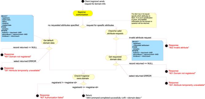
Figure 44: Query domain
QUERY CLUSTER
The
QUERY CLUSTER command is used for retrieving information about the name server
entries of a cluster object. The request must contain exactly one “cluster-id”
attribute identifying the cluster object.
The
server must return all the name server entries in the cluster.
Example
query:
QUERY CLUSTER SRRP/1.0
registrar-id=123456789
registrar-auth=pass-phrase
cluster-id=987654321
This
request indicates that the client wants a list of the name servers in cluster
object. The output could look like this:
200 Command completed successfully
ns1-address=128.39.19.168
ns1-name=ns1.example.com
ns2-address=128.39.19.169
ns2-name=ns2.example.com
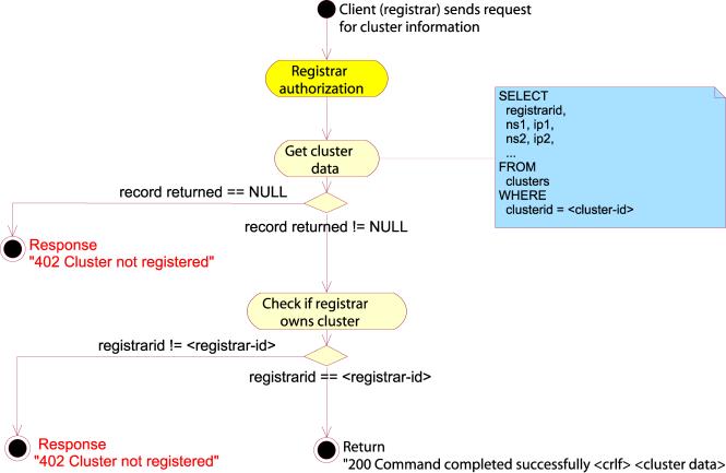
Figure 45: Query cluster
TRANSFER
The
TRANSFER command is used for requesting and approving the transfer of a domain
from one Registrar to another.
TRANSFER DOMAIN
This command
is used for requesting a transfer of a domain belonging to another Registrar to
the requesting Registrar. The request body must contain the requested domain
name in the attribute “domain-name” and the domain password in the
"domain-auth" attribute.
If the
domain is not registered, the server should issue a 401 Domain not registered.
If the domain password did not properly authorize the transfer, the server
should issue a 412 Authorization failed error message.
Note
that information regarding domain transfers, such as domain passwords and
notification about lost and obtained domains, is not handled by SRRP. Out of
band communications means should be used for this purpose.
Example:
TRANSFER DOMAIN SRRP/1.0
registrar-id=234567890
registrar-auth=pass-phrase
domain-name=example.com
domain-auth=domain-pass-phrase
Here,
the domain example.com is requested transferred to the requesting Registrar. If
the domain password is correct, the domain server should immediately transfer
the ownership of the domain to the requesting Registrar.
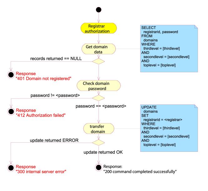
Figure 46: Transfer domain
STATUS
The
STATUS commands give information about the implementation and configuration of
the server.
STATUS DEFAULTS
The
STATUS DEFAULTS command is used for retrieving various default values, such as
default status and default registration period, from the server.
The
response body MUST contain the following attributes:
·
The
default status for new registrations in the “default-status” attribute
·
The
default registration period, in months, for new registrations in the
“default-period” attribute.
·
The
maximum user definable registration period, zero (0) if unset or unlimited, in
the “maximum-period” attribute.
·
The
default domain transfer response in the “transfer-default” attribute. Valid
values are the ASCII strings “yes”, “no” or “unset”.
·
The
transfer timeout period in the “transfer-timeout” atribute. If this is set to
zero (0), the feature is disabled and both this attribute and
“transfer-default” SHOULD be ignored.
·
The
minimum number of name servers allowed in the “minimum-ns” attribute, zero (0)
if unspecified.
·
The
maximum number of name servers allowed in the “maximum-ns” attribute, zero (0)
if unspecified.
The
server MAY add additional “text” attributes for returning server specific
defaults. The client MUST NOT rely on these “text” attributes.
Example
command:
STATUS DEFAULTS SRRP/1.0
registrar-id=123456789
registrar-auth=pass-phrase
A
typical response message would look like this:
200 Command completed successfully
default-status=active
default-period=66
maximum-period=120
domain-transfer=unset
transfer-timeout=0
minimum-ns=2
maximum-ns=8
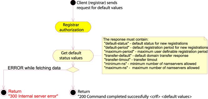
Figure 47: Status default
STATUS SERVER
Clients
may use a STATUS command with the SERVER argument to fetch information about
the server implementation. The information is returned in one or more “text”
attributes. If the server does not wish to return any information, it can do so
by returning a 200 Command completed successfully and leave the response body empty.
The
server MAY return information on a STATUS SERVER command, but the client MUST
NOT rely on this information.
Example:
STATUS SERVER SRRP/1.0
registrar-id=123456789
registrar-auth=pass-phrase
The
response message may look like this:
200 Command completed successfully
text=Standard SRRP server version 1.0.4p3
text=Compiled 2001-01-29 03:58:32 GMT+1

Figure 48: Status server
Response codes
Success
codes (2xx)
There is
only one success code, and it indicates unconditional success.
200 Command completed successfully
This
response code indicates unconditional success when executing the requested
command. It is the only success code.
Temporary
error codes (3xx)
Temporary
error codes indicate that the requested command could not be executed due to a
temporary failure. The client MAY retry the command later.
300
Internal server error
The
server suffered from a fatal internal error, and the client is advised to
notify the server administrator and retry the operation later. The server
SHOULD present contact information in the error message, log the error and
notify the server administrator.
301
Attribute temporarily unavailable
This
error code indicates that the server was unable to return a mandatory attribute
due to a temporary failure.
Permanent
error codes (4xx)
Permanent
error codes indicate that the requested command could not be executed due to a
permanent failure. The client SHOULD NOT retry the command.
400 Domain already registered
This error code signals that the client has attempted to register an object that is already registered.
401 Domain not registered
This indicates that the client attempted to operate on an domain which is not registered.
402 Cluster not registered
This indicates that the client attempted to operate on an cluster which is not registered.
403 Invalid attribute
The request body contained one or more invalid attributes, indicating a client error or protocol mismatch.
404 Invalid attribute value
The request body contained one or more invalid attribute values. This could be a character string where the server expected a number, or an incomplete data string.
405 Invalid expire date
The client specified an expiry date which was either in the past or too far in the future.
406 Invalid number of name servers
The client specified either too few or too many name servers.
407 Mandatory attribute missing
This indicates that a mandatory attribute was missing.
408 Removal not permitted
The client attempted to remove an entity which is required, for instance a cluster object which is in use by one or more domain objects.
409 Blocked domain
The domain which the client attempted to register was blacklisted by the server.
410 Credit failure
The client attempted to execute a command for which there was not enough credit.
411 Access denied
The client attempted an unauthorized operation. The server should log such errors.
412 Auhorization failed
The authorization credentials specified by the client did not match, or the registrar ID was unknown.
413 Unsupported protocol version
The client specified an unsupported protocol, either too new or old.
ABNF Definition of SRRP
This is
a formal definition of SRRP using standard ABNF as defined in [3].
Lexical
definitions
SP = %x20 ; ASCII space
HT = %x09 ; ASCII horizontal tab
DOT = %x2e ; ASCII “.”
EOF = %x00 ; ASCII end of file
DASH = %x2d ; ASCII “-“
SL = %x2f ; ASCII “/“
EQ = %x3d ; ASCII “=”
CR = %x0D ; ASCII carriage return
LF = %x0A ; ASCII linefeed
LWS = SP / HT ; linear white space
CRLF = CR LF ; carriage return line feed sequence
UALPHA = %x41-5a ; ASCII A-Z
LALPHA = %x61-7a ; ASCII a-z
ALPHA = UALPHA / LAPLHA ; ASCII a-z / A-Z
DIGIT = %x30-39 ; ASCII 0-9
PCHAR = ALPHA / DIGIT / DASH ; protocol characters
UCHAR = %x20-%ff ; user characters
Basic
grammatical definitions
ip-address = 1*3DIGIT DOT 1*3DIGIT DOT 1*3DIGIT DOT 1*3DIGIT
protocol = “SRRP” SL version
version = main-version DOT sub-version
main-version = 1*DIGIT
sub-version = 1*DIGIT
date = year DASH month DASH day
year = 4DIGIT
month = 2DIGIT
day = 2DIGIT
response-header = success-header / tempfail-header / permfail-header
success-header = success-code LWS response-text
tempfail-header = temporary-fail-code LWS response-text
permfail-header = permanent-fail-code LWS response-text
success-code = “2” 2DIGIT
temporary-fail-code = “3” 2DIGIT
permanent-fail-code = “4” 2DIGIT
response-text = *PCHAR
standard-response-message = response-header [CRLF response-body]
response-body = 1*text-pair
error-response-message = (tempfail-header / permfail-header)
[CRLF response-body]
Attribute/value
set definitions
attribute-value-pair = attribute EQ value CRLF
attribute = 1*PCHAR
value = *UCHAR
text-pair = text-attribute EQ text-value CRLF
text-attribute = “text”
text-value = *UCHAR
cluster-id-pair = cluster-id-attribute EQ cluster-id-value CRLF
cluster-id-attribute = “cluster-id”
cluster-id-value = 1*PCHAR
status-pair = status-attribute EQ status-value CRLF
status-attribute = “status”
status-value = “active” / “inactive”
registrar-id-pair = registrar-id-attribute EQ registrar-id-value CRLF
registrar-id-attribute = “registrar-id”
registrar-id-value = 1*PCHAR
registrar-auth-pair = registrar-auth-attribute EQ registrar-auth-value CRLF
registrar-auth-attribute = “registrar-auth”
registrar-auth-value = *UCHAR
expiry-date-pair = expiry-date-attribute EQ expiry-date-value CRLF
expiry-date-attribute = “expiry-date”
expiry-date-value = date
domain-name-pair = domain-name-attribute EQ domain-name-value CRLF
domain-name-attribute = “domain-name”
domain-name-value = 1*UCHAR
domain-auth-pair = domain-auth-attribute EQ domain-auth-value CRLF
domain-auth-attribute = "domain-auth"
domain-auth-value = *UCHAR
get-specific-pair = get-specific-attribute EQ get-specific-value CRLF
get-specific-attribute = “get-specific”
get-specific-value = 1*PCHAR
name-server-entry = ns-address-pair ns-name-pair
ns-address-pair = ns-address-attribute EQ ns-address-value CRLF
ns-address-attribute = “ns” 1*DIGIT “-address”
ns-address-value = ip-address
ns-name-pair = ns-name-attribute EQ ns-name-value CRLF
ns-name-attribute = “ns” 1*DIGIT “-name”
ns-name-value = UCHAR
registrar-auth-entry = registrar-id-pair registrar-auth-pair
Message
definition
message = (create / set / delete / query / transfer / status) EOF
create = create-domain / create-cluster
set = set-expire / set-cluster / set-status / set-nameservers
delete = delete-domain / delete-cluster
query = query-domain / query-cluster
transfer = transfer-request / transfer-response
status = status-defaults / status-server
create-domain = create-domain-request / create-domain-response
create-cluster = create-cluster-request / create-cluster-response
set-expire = set-expire-request / set-expire-response
set-cluster = set-cluster-request / set-cluster-response
set-status = set-status-request / set-status-response
set-nameservers = set-nameservers-request / set-nameservers-response
set-password = set-password-request / set-password-response
delete-domain = delete-domain-request / delete-domain-response
delete-cluster = delete-cluster-request / delete-cluster-response
query-domain = query-domain-request / query-domain-response
query-cluster = query-cluster-request / query-cluster-response
transfer-domain = transfer-domain-request / transfer-domain-response
status-defaults = status-defaults-request / status-default-response
status-server = status-server-request / status-server-response
; CREATE DOMAIN REQUEST
create-domain-request = create-domain-request-header CRLF
create-domain-request-body
create-domain-request-header = “CREATE” LWS “DOMAIN” LWS protocol
create-domain-request-body = registrar-auth-entry domain-name-pair
domain-auth-pair [expiry-date-pair] [status-pair] (cluster-id-pair /
*name-server-entry)
; CREATE DOMAIN RESPONSE
create-domain-response = create-domain-success / error-response-message
create-domain-success = success-header CRLF cluster-id-pair status-pair
expiry-date-pair
; CREATE CLUSTER REQUEST
create-cluster-request = create-cluster-request-header CRLF
create-cluster-request-body
create-cluster-request-header = “CREATE LWS “CLUSTER” LWS protocol
create-cluster-request-body = registrar-auth-entry *name-server-entry
; CREATE CLUSTER RESPONSE
create-cluster-response = create-cluster-success / error-response-message
create-cluster-success = success-header CRLF cluster-id-pair
; SET EXPIRE REQUEST
set-expire-request = set-expire-request-header CRLF set-expire-request-body
set-expire-request-header = “SET” LWS “EXPIRE” LWS protocol
set-expire-request-body = registrar-auth-entry expiry-date-pair
domain-name-pair
; SET EXPIRE RESPONSE
set-expire-response = standard-response
; SET CLUSTER REQUEST
set-cluster-request = set-cluster-request-header CRLF set-cluster-request-body
set-cluster-request-header = “SET” LWS “CLUSTER” LWS protocol
set-cluster-request-body = registrar-auth-entry cluster-id-pair
domain-name-pair
; SET CLUSTER RESPONSE
set-expire-response = standard-response
; SET STATUS REQUEST
set-status-request = set-status-request-header CRLF set-status-request-body
set-status-request-header = “SET” LWS “STATUS” LWS protocol
set-status-request-body = registrar-auth-entry domain-name-pair status-pair
; SET STATUS RESPONSE
set-expire-response = standard-response
; SET NAMESERVERS REQUEST
set-nameservers-request = set-nameservers-request-header CRLF
set-nameservers-request-body
set-nameservers-request-header = “SET” LWS “NAMESERVERS” LWS protocol
set-nameservers-request-body = registrar-auth-entry cluster-id-pair
*name-server-entry
; SET NAMESERVERS RESPONSE
set-expire-response = standard-response
; SET PASSWORD REQUEST
set-password-request = set-password-request-header CRLF
set-password-request-body
set-password-request-header = "SET" LWS "PASSWORD" LWS protocol
set-password-request-body = registrar-auth-entry domain-name-pair
domain-auth-pair
; SET PASSWORD RESPONSE
set-password-response = standard-response
; DELETE DOMAIN REQUEST
delete-domain-request = delete-domain-request-header CRLF
delete-domain-request-body
delete-domain-request-header = “DELETE” LWS “DOMAIN” LWS protocol
delete-domain-request-body = registrar-auth-entry domain-name-pair
; DELETE DOMAIN RESPONSE
delete-domain-response = standard-response
; DELETE CLUSTER REQUEST
delete-cluster-request = delete-cluster-request-header CRLF
delete-cluster-request-body
delete-cluster-request-header = “DELETE” LWS “CLUSTER” LWS protocol
delete-cluster-request-body = registrar-auth-entry cluster-id-pair
; DELETE CLUSTER RESPONSE
delete-domain-response = standard-response
; QUERY DOMAIN REQUEST
query-domain-request = query-domain-request-header CRLF
query-domain-request-body
query-domain-request-header = “QUERY” LWS “DOMAIN” LWS protocol
query-domain-request-body = registrar-auth-entry domain-name-pair
[get-specific-pair]
; QUERY DOMAIN RESPONSE
query-domain-response = full-domain-response / specific-domain-response /
error-response-message
full-domain-response = success-header CRLF *attribute-value-pair
specific-response = success-header CRLF attribute-value-pair
; QUERY CLUSTER REQUEST
query-cluster-request = query-cluster-request-header CRLF
query-cluster-request-body
query-cluster-request-header = “QUERY” LWS “CLUSTER” LWS protocol
query-cluster-request-body = registrar-auth-entry cluster-id-pair
; QUERY CLUSTER RESPONSE
query-cluster-response = standard-response
; TRANSFER DOMAIN REQUESTtransfer-domain-request = transfer-domain-request-header CRLF
transfer-domain-request-body
transfer-domain-request-header = “TRANSFER” LWS “REQUEST” LWS protocol
transfer-domain-request-body = registrar-auth-entry domain-name-pair
; TRANSFER DOMAIN RESPONSE
transfer-domain-response = standard-response
; STATUS DEFAULTS REQUEST
status-defaults-request = status-defaults-request-header CRLF
status-defaults-request-body
status-defaults-request-header = “STATUS” LWS “DEFAULTS” LWS protocol
status-defaults-request-body = registrar-auth-entry
; STATUS DEFAULTS RESPONSE
status-defaults-response = status-defaults-response-message /
standard-error-message
status-defaults-response-message = success-header CRLF
status-defaults-response-body
status-defaults-response-body = default-status-pair / default-period-pair /
maximum-period / transfer-default / text-pair /
transfer-timeout / minimum-ns / maximum-ns
default-status-pair = default-status-attribute EQ default-status-value CRLF
default-status-attribute = “default-status”
default-status-value = “active” / “inactive”
default-period-pair = default-period-attribute EQ default-period-value CRLF
default-period-attribute = “default-period”
default-period-value = 1*DIGIT
maximum-period-pair = maximum-period-attribute EQ maximum-period-pair CRLF
maximum-period-attribute = “maximum-period”
maximum-period-value = 1*DIGIT
transfer-default-pair = transfer-default-attribute EQ transfer-default-value
CRLF
transfer-default-attribute = “transfer-default”
transfer-default-value = “yes” / “no” / “unset”
minimum-ns-pair = minimum-ns-attribute EQ minimum-ns-value CRLF
minimum-ns-attribute = “minimum-ns”
minimum-ns-value = 1*DIGIT
maximum-ns-pair = maximum-ns-attribute EQ maximum-ns-value CRLF
maximum-ns-attribute = “minimum-ns”
maximum-ns-value = 1*DIGIT
; STATUS SERVER REQUEST
status-server-request = status-server-request-header CRLF
status-server-request-body
status-server-request-header = “STATUS” LWS “SERVER” LWS protocol
status-server-request-body = registrar-auth-entry
; STATUS SERVER RESPONSE
status-server-response = status-server-response-message /
standard-error-message
status-server-response-message = success-header CRLF
status-server-response-body
status-server-response-body = *text-pair
RRP to SRRP mapping
As RRP
is a state based protocol, i.e. requires the server to maintain state
information for every connected client for as long as he is connected, it is
impossible for a RRP client to talk directly to an SRRP server. The only way to
allow for RRP clients to talk to SRRP servers, would be to use an RRP/SRRP
gateway to maintain the state required by the RRP client, and issue SRRP
messages for every RRP operation the client performs. This is, however, outside
of the scope of this document.
References
[1]
Bradner, S., “Key Words for Use in RFCs to Indicate Requirement
Levels”,
BCP 14, RFC 2119, March 1997.
[2] A. Frier, P. Karlton, and P. Kocher, “The
SSL 3.0 Protocol”,
Netscape
Communications Corp., November 18, 1996.
[3] Crocker, D. (Editor) and P. Overell,
“Augmented BNF for Syntax
Specifications:
ABNF”, RFC 2234, November 1997.
Error handling
In the case where the Registry receives an SRRP command from a Registrar that writes something to the database, there is always the possibility that an error will occur so that the Registrar client software never receives the returned success message. If this is the case, it is up to the Registrar client software to detect that this return message is never received, and then to act upon this, either by attempting to register the domain again, or by querying the Registry database to see if the correct information was entered. The Registry will not try to intercept or correct such errors.
Mapping from SRRP to the RRP as defined in RFC 2832
RRP/SRRP mapping
RRP and
SRRP have a different approach to the same problem, and as RRP clients are
already widespread there may be an application for an RRP-to-SRRP gateway.
There is no direct mapping between RRP and SRRP, but most commands can be
easily converted. It is the Registry’s intention to provide a RRP interface for
the Registrars who wish to use their existing protocol implementation and not
the API provided by GNR.
Basic gateway operation
The
gateway will receive one RRP-command and must report back to the client if it
was successful or not. Some commands do not have an SRRP-equivalent, and the
gateway must choose between reporting back an error or a fake success code.
Normally, the first alternative is preferred.
In other
cases, the commands have SRRP-equivalents which function in a different manner.
In this case the gateway will have to perform a translation between the
RRP-commands and the SRRP-commands, if necessary by maintaining state
information itself.
There
are three basic problems that have to be overcome:
·
Some
operations, which require several RRP-commands, must be done in a single
SRRP-command.
·
SRRP
groups name servers into clusters, RRP does not
·
Some
RRP-commands do not have a direct equivalent in SRRP, and vice versa.
Mapping multiple RRP-commands on to one SRRP-command
This
problem is simplified by the fact the RRP may send several commands in batch,
and this batch may be used by the mapping function of the gateway. For
instance, take this RRP-session:
add
EntityName:NameServer
NameServer:ns1.example.com
IPAddress:161.92.114.198
.
add
EntityName:NameServer
NameServer:ns2.example.com
IPAddress:161.92.114.199
.
The
client creates two name servers identified by their DNS-name. The gateway
should accept both these commands, translate them into a SRRP-message that
might look like this:
CREATE CLUSTER SRRP/1.0
registrar-id=123456789
registrar-auth=pass-phrase
ns1-name=ns1.example.com
ns1-address=161.92.114.198
ns2-name=ns2.example.com
ns2-address=161.92.114.199
This
transaction would work nicely; the “registrar-id” and “registrar-auth”
attributes are known by the gateway from the establishment of the session,
through the “Id” and “Password” parameters in the RRP “session” command.
As the
SRRP-server may impose a minimum number of name servers for a cluster object,
the gateway must check this with the server through the “STATUS DEFAULTS”
command, and if necessary cache the required number of RRP-commands.
In SRRP,
name servers are grouped in logical entities termed clusters. As RRP has no
mechanism for such a grouping, the name servers are grouped in a cluster as
they are created. If the client specifies too few name servers before issuing
another command, the gateway must signal an error to the client.
The
gateway must maintain the relationships between the name server names (which
are used as identifiers in RRP) and their assigned cluster IDs (which are used
as identifiers in SRRP) internally.
This
mapping is essential as every RRP-request will refer to the name server name of
one or more name servers, while the SRRP-request sent by the gateway must refer
to the name server’s cluster ID.
Handling name server clusters through RRP
When
dealing with clusters, the SRRP server leaves most of the work to the client.
No matter what a client wants to do with a name server’s cluster, it has to
obtain a list of name servers through the QUERY CLUSTER command, manipulate it
and write it back to the server. This moves some of the complexity from the
server to the client, but increases overall flexibility and simplicity.
However,
this makes things more complex for the gateway as there is no natural mapping
from a RRP-command referring to a name server and the cluster of name servers
used by SRRP. Thus, the gateway has to maintain a mapping between the name
server names used by RRP and the clusters they belong to on the SRRP server.
For
example, when deleting a name server through the RRP “del” command, an RRP
client would perform a command like this:
del
EntityName:NameServer
NameServer:ns1.example.com
The
gateway must use its internal name server map to get the cluster ID that this
name server belongs to. Then it must retrieve all the name servers in this
cluster:
QUERY CLUSTER SRRP/1.0
registrar-id=123456789
registrar-auth=pass-phrase
cluster-id=987654321
This
will give the gateway a complete list of all the name servers in the cluster.
It must now remove the name server in question from the list, and issue a SET
NAMESERVERS command to update the cluster:
SET NAMESERVERS SRRP/1.0
registrar-id=123456789
registrar-auth=pass-phrase
cluster-id=987654321
ns1-name=ns2.example.com
ns2-address=135.94.18.121
ns3-name=ns3.example.com
ns3-address=135.94.18.121
The name
server ns1.example.com will now be deleted.
Handling unsupported RRP commands
Some RRP
commands are impossible to support in SRRP, others are not necessary. An
example of the first is the “transfer” command in RRP, and the “session”
command of the latter.
If the
command is unsupported, the gateway should simply issue a meaningful error
code. If the command is not supported because it is useless for a stateless
protocol, it should be accepted with a success code.
Some commands,
notably the “session” command, provides necessary information, namely the user
ID and password of the client. This information is needed by the gateway for
further communication on behalf of the client, and it must store this for later
use. The gateway may also perform a harmless command to actually verify the
user ID and password, though it will be noticed on the next client command if
it is a mismatch.
RRP to SRRP command mapping
RRP command SRRP command(s) Comment
command entity
add Domain CREATE DOMAIN
add NameServer CREATE CLUSTER
query Domain [3]
query NameServer [3]
del Domain DELETE DOMAIN
del NameServer SET NAMESERVERS [1]
describe STATUS SERVER
mod Domain SET STATUS, CREATE CLUSTER
mod NameServer SET NAMESERVERS [1]
quit [2]
renew Domain SET EXPIRE
session [2]
status Domain QUERY DOMAIN
status NameServer QUERY CLUSTER
transfer request [3]
transfer response [3]
Comments:
1)
As
SRRP does not actually support deleting a single name server, the gateway will
have to obtain the name servers contained in the cluster (for instance through
the QUERY CLUSTER command), and use the SET NAMESERVERS command to set all the
name servers of the cluster except the deleted one.
2)
Has
no direct equivalent in SRRP, as this command is specific for state based
protocols.
3)
Not
supported or incompatible command
D15.2.3 Database capabilities
The database will mostly communicate with the Registry server, which will be responsible for all writing to the database from the SRRP interface, as well as automatic updates of the WHOIS and DNS systems. The database will also communicate with the Registrar web interface, and the billing system.
The logical database will actually consist of 2 databases that are exact replicas of one another. The Registry server will be responsible for the communication with these databases. The reason for using 2 databases like this is to get error detection. When an SRRP transaction that writes something to the database is received, the Registry server will write this to both databases, and compare the database responses. If these differ, one of the databases has made an error, and the Registry server will halt all database transactions. Another cause of a complete halt is, in case of an update, ifthe Registry server reads information from the databases to be sent to the update server, and the replies from the databases differ. All must be halted because we don’t necessarily know at this point which database has the error, so subsequent reads or writes may both be wrong in some way. In the case of a difference between the 2 databases, system recovery will begin immediately, and this is a manual job to locate and repair the error, either by fixing the database or by making a complete backup recovery.
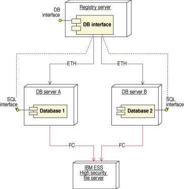
Figure 49: Two separate databases are operated simultaneously, to ensure duplicate data and error detection
There is no sun-rise period in the system due to immediate update scheme employed. The WHOIS and DNS are updated continuously, so there will be no periods with high load after the updates have been made. When operation starts of the top level domain, extremely high loads are expected, and these will be stopped at the SRRP server level, so we can always control what happens at the Registry server and database levels.
Database structure
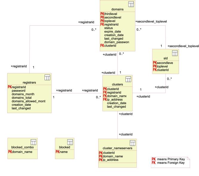
Figure 50: The ER diagram of the database
Figure: The ER diagram of the database
Table Descriptions:
Domains
This table contains all information about the single domains, like when it expires, what nameserver-cluster it uses, and what it’s status is. All columns must be NOT NULL.
SLD
This table is made to allow distribution of nameservers for domains on the second level. When the registry only allows registrations on third level domains, there is the possibility to register many more domains than is possible on second level domains, and when there are a lot of domains registered, this may be necessary. Also, the introduction of IPv6 will make DNS become a much more complex application, which will again create the necessity to distribute the load. In the beginning, we will for example start distributing all domains starting with a-m on the second level to one nameserver cluster and the rest, n-z, on another nameserver cluster. In the beginning it is not necessary to use this table. All columns must be NOT NULL.
Clusters
The clusters table contains all the cluster-ids and the respective nameservers. At least 2 nameservers must be in a cluster for it to be valid. All columns must be NOT NULL.
Registrar
This table contains all the registrar information needed in the database, including billing information and the registrar password. All columns must be NOT NULL.
Cluster_Nameservers
This table contains all the clusterids with all the belonging domain names and IP addresses. All columns must be NOT NULL.
Blocked
The Blocked table contains all the words that are blocked on second and third level domains. All columns must be NOT NULL.
Blocked_combo
This table contains all the combinations of third level and second level domains that are blocked. All columns must be NOT NULL.
Database software, hardware and performance
The database is a db2 running on the AIX operating system on two IBM RS/6000 6 way M80 in parallel. It is designed to handle 40 domain name registrations pr second.
Scaling for future load
In case
the Registry will experience significantly higher load than anticipated, or in
the case of extremely large volumes, the system is envisioned to scale through
the use of high-availability cluster multiprocessing.
IBM’s HACMP is the “High Availability Cluster MultiProcessing” software for AIX Version 4.3, providing heartbeat monitoring of one system from another. When one system detects that the other has failed (and it can distinguish between failure of the other system and failure of a network or a network adapter) – it takes over the IP address of the failing system and takes over the applications from the failed system. This also allows failover across geographically dispersed systems, thus guarding against the possibility that an entire data centre might be taken out.
See the D15.2.3 section in the IBM part of the proposal for further descriptions of the database’s hardware component.
Domain transfers in the database
When a Registrant wants to transfer a domain from Registrar A to Registrar B, the following procedure will be used:
1) The Registrant has a domain password, and contacts Registrar B, requesting the domain transfer. The Registrant must now supply this password to Registrar B. (If the transfer-password is lost/forgotten, it can be sent from the Registry to the contact details provided on the domain name)
2) Registrar B contacts the Registry (with SRRP), and requests a transfer of the domain from Registrar A to Registrar B, authenticating the request with both it’s own password and the customer’s domain password.
3) The Registry verifies that both passwords are correct, and immediately transfers the domain from Registrar A to Registrar B, charging Registrar B for a one year registration, and adding one year to the expiry date of the domain.
4) The domain has now been successfully transferred to another Registrar.
D15.2.4 Zone file generation
For this section, refer also to D15.2.5, as the generation of Zone files, and their distribution is closely linked due to the continuous updates of zone files.
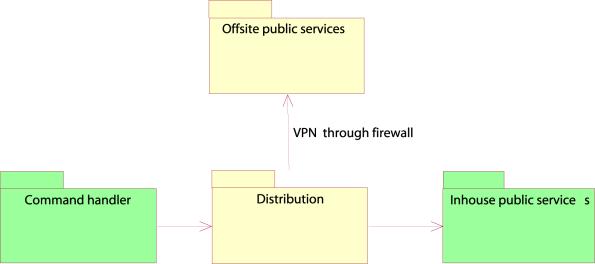
The maintenance of the DNS and the whois server information is described in this chapter. The main components that are involved in this action are to be found in the distribution component. This contains the interface towards inhouse and offsite services as well as the offsite log. The distribution server is both primary stealth DNS server, and whois update server. (See chapter 15.2.5)
The update process
When the command handler has completed a relevant change of domain data (insert, transfer or delete), a message containing the changed data is sent to the distribution component. These changes immediately initiate an update of the zone file in the DNS server software, which resides in the distribution software. The changes are also logged to an external log system immediately. The change/update processes are illustrated in the following diagram:
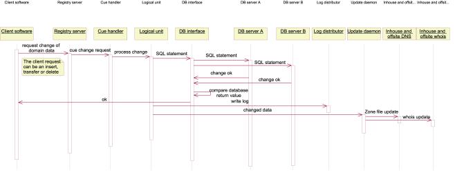
A client initiates a change of some domain data. The command handler receives and processes the request. When both databases have fulfilled the task and responded positively, the logical unit in the command handler sends the change to the distribution software (update daemon), which updates the zone file and whois information.
These processes are described more in detail in chapter 15.2.5.
Security and reliability
The zonefile is the prime responsibility of the Registry and is strictly controlled. It updated by the Registry only, and the as Registrars insert, delete or otherwise modify the contents of the database, the changes are continuously reflected in the zonefile. Authentication of the Registrars is severe and security is high due to the hardware encryption of the communication.
All interaction between the registry and the registrars over (S)RRP is logged, so no further logging is necessary. The database is backed up regularly. The update server will be connected to the ESS (Enterprise Storage System), which will also be backed up regularly. See D15.2.7 for more information on this.
If the two databases do not respond with the same answer, this implies that one of the databases is down or corrupt, so updates will be halted and manual measures must be taken immediately. If this happens, a complete zonefile will be regenerated and distributed once the databases are running normally again.
In the case that manual interaction with the database is necessary, a complete incident log must be filed, so that this can be tracked down. Only authorized personnel may have access to the database.
D15.2.5 Zone file distribution
Locations of DNS servers
The external DNS servers will be residing in Asia, USA and central Europe, with new locations possible to add as load grows. The servers will be placed on at least two different backbone networks in colocation centres. Since none of the backbones have 100% reliability, the use of several backbones will make it extremely unlikely that the DNS service will be down, since it is conditional upon all backbones going down simultaneously or in the same time-window. The scalability of the DNS server distributed network is high, and it can rapidly be added new DNS centers in different parts of the world to compensate for an eventual higher load than foreseen.
It is foreseen that future scaling of the system will split the domain names on to different nameservers, so each nameserver does not serve all domain names, but only one part of the zone. This split could i.e. be done alphabetically, A-M to one set of nameservers, N-Z to another.
Distribution of Zone File
The DNS servers will all be continuously updated from the Update Server, which is running as stealth primary DNS. We aim to use BIND9, developed by ISC, which will support the DNS extensions necessary to allow Incremental Zone Transfers (IXFR). Our update server will run a stealth primary DNS server, which will be dedicated to doing updates to our DNS servers with the AXFR and/or IXFR mechanisms of DNS. This server will not be visible to the rest of the world, and it will be connected to our external DNS servers with hardware encrypted VPN cards, to the internal DNS servers it uses the internal network. This is to ensure that the data arrives at the intended destination without tampering or sniffing on the way. TSIG will also be employed to verify that the data transmitted comes from the correct source and arrives at the correct destination.
Figure 53:Logical map of the distribution of the zone
files (and WHOIS)
Software diversification on DNS
We will use BIND9 for the main DNS servers and for the initial external DNS locations, but aim to use another application to provide additional redundancy and security. For this purpose we aim at installing DJBDNS, developed by D J Bernstein, as a supplementary DNS server. DJBDNS is a different application than BIND, not developed by the same person or group, and these two applications should not possess the same flaws. In the case of a fatal breakdown of all BIND application, or a major security hole, we will have redundancy from the DJBDNS server which should not be affected by the same potential problem.
Errors are highly unlikely to be present at the same time in both servers running different applications, so if any of these errors cause an incident, we will not lose the availability of the DNS service
D15.2.6 Billing and collection systems
The prime principle of registrations is that the domain name registrations are prepaid, either in the form of a credit limit, or an actual prepayment of a certain size. This can be in combination with an insurance bond from the Registrar, like today’s 100,000 USD demanded from ICANN.
The billing and collection systems need not be complicated since the Registry’s billing relations are with the Registrars alone.
Billing process for domain name registration:
· Request registration (Password acknowledged)
· Credit check in database
· Insert domain name
· Acknowledge registration
When a registration is done, the Registrar’s account balance is debited with the price for one registration. Registrations continue as long as the balance is positive, or until a credit limit, if any, is exceeded.
Once a month, the Registrar is billed with the amount necessary for next month’s registrations. This amount can be chosen by the Registrar itself and can vary from month to month. Any negative balances, if allowed, will be payable on 30 days notice.
The billing system and account system will be delivered from SAGE, from the Line 50 series. The system is simple, stable, and used by more than 2 million small and medium sized enterprises around the globe. There will be an automated generation of invoices according to the Registrar’s balance, and payments from Registrars are expected by wire transfer. (documentation from SAGE is attached in Appendix.D.2.3)
The billing at the end of the month happens in the following way:
· Accountant generates list of all registrars, with no of domain names registered this month, and total no of registrations (for verifications). For each registrar, a list of every domain registered for this billing period will be taken out.
· The data goes in to the billing system and invoices are generated, printed out and sent by email and physical post.
The security of the system is assured by its manual nature. As long as the number of registrars is feasibly handled with automated generation of invoices and report generation from the database, the process can be handled by an accountant. Additional recruiting of accountants can scale to higher number of Registrars. The financial controller will ensure that no errors are committed as is common practice among financial controllers.
The Registrar can access the billing information and account status through the secure www interface (SSL), and request the information needed. The support team, key account manager and accountants are also available on telephone support for this purpose, should extra information be needed.
D15.2.7 Data escrow and backup
Backup
GNR ltd will
with all means possible try to ensure high data integrity and security, and we
will create very strict disaster recovery plans for data stored by GNR ltd. One
central component to ensure this goal is the internal backup solution and the
policies associated with these.
Internal backup
The
backup solution takes care of all internal backup needs at GNR ltd. The system
is built on components delivered from IBM and on software from Tivoli. This
combination of software and hardware ensures a highly secure and automated
backup system. Backup policy is implemented using the Tivoli backup software
and takes care of issues like scheduling tape sets for offline storage use.
Backups are taken while the system is running, so operations need not be
stopped or halted for backup.
More
information on the backup system and the hardware can be found in the IBM part
of the proposal.
External backup
Since the
nature of tape backup is a point in time process, GNR ltd will implement
essential systems to make sure that critical data is not lost between
backup-cycles. All records needed to reconstruct the system will be considered
as critical data. The way GNR ltd will ensure that this is accomplished is to
make a real time offsite journal of all changes made to the database records in
the Registry system. This will enable GNR ltd to reconstruct the whole Registry
if a disaster affects the operation.
Data
Escrow
In addition to what GNR ltd feels is a safe and flexible backup-solution, we place additional data security by depositing data to an escrow service. This will place additional data security on the organisational level in that we actually deposit data in case a conflict occurs. The escrow function will be taken care of by the US company SourceFile, and will work by GNR ltd submitting data to the escrow service on a predefined schedule. The escrow agent will ensure that data is protected and is made available to the correct owner if a legal dispute should occur.
Data is transferred in a strongly encrypted form to the
Escrow agent over the Internet, after which SourceFile stores deposits in secure vaulting facilities designed to
hold electronic items.

Figure 54: The storage facility location of Sourcefile
For more information about the service and agreement from Sourcefile, see Appendix.D.2.3.
D15.2.8 WHOIS SERVICE
A WHOIS service able to handle a sustained and significant load will be set up. The available WHOIS servers will be both situated in the main data centre, on a high availability active/active load balanced failover system, and in external sites located with the external DNS servers. New servers can be easily added.
The software will be created in-house, and will be similar to the WHOIS service found today on whois.crsnic.net. Internally, this software will be tailored to handle fast searches. The WHOIS service will only give replies for exact matches of the domain name. Search capabilities beyond this will be implemented should the policy development allow it.
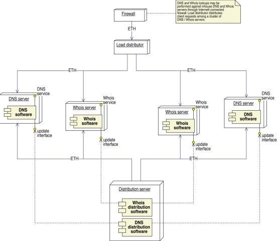
Figure 55: Usage of the WHOIS system
Output of the WHOIS
Standard output will look like this:
Domain Name: Hakon.Haugnes.name
Registrar: RegistrarA Inc.
Registrar Whois: whois.registrarA.inc
Registrar URL: www.RegistrarA.inc
Nameserver: ns1.registrarA.net
Nameserver: ns2.registrarA.net
Modified: 2001-01-01
The WHOIS server given in this output will be the Registrar's WHOIS server where further information will be supplied. If there are more than 2 nameservers, only the first 2 will be given in the WHOIS output.
The WHOIS software will be built around a simple yet very efficient file structure. For example, if someone queries the domain "JOHN.SMITH.NAME", we will look for the file "name/smith/john". If this file exists, the contents of this file will be printed to the WHOIS client. If the file does not exist, the server will reply that the domain is free. This allows for a system that is easy to implement, extremely rapid and easily updateable on a continuous basis.
Updates
All the WHOIS servers, internal and offsite, will run an update server application that will only be accessible from the internal network (separate network cards) in the case of the servers located in the main datacenter, and only through the hardware encrypted VPN cards in the case of the external WHOIS servers. This server application will nonetheless be made as simple and secure as possible. The chroot() system call will be used to restrict the application to a directory, so hackers will not be able to gain access to the system configuration if they get in. The server application will run as a user with low permissions.
To update information on the WHOIS server, client software on the update server will connect to the update server application on the WHOIS server. A typical transfer will look like this:
set alexander.smith.name\n
Domain Name: alexander.smith.name\n
Registrar: The Internet Registrar Company Inc.\n
Registrar Whois: whois.intreg.com\n
Registrar
URL: www.intreg.com\n
Nameserver: ns1.dnshost.com\n
Nameserver: ns2.dnshost.com\n
Modified: 2001-02-17\n
.\n
The update server application on the WHOIS server will read this information, and when it receives a single line consisting of a period only, it will return a confirmation to the client and immediately disconnect.
The first line received will specify what to do and the name of the domain. Two (2) commands will be allowed, “set” and “delete”. If the command is “set”, the update server application on the WHOIS server will read the complete information on the next lines. With the directory hierarchy structure proposed above, the application will know where to place the file containing the information. If the command is “delete”, the WHOIS information for this domain will be deleted.
While the information is being received, it is written to a temporary file on the same filesystem that the resulting file will be placed on. When the transfer is completed, this temporary file will be renamed to the correct name, in this case name/smith/alexander. This will ensure that partial files will never be sent if someone queries a domain while it is being updated, regardless of whether it is the first time WHOIS information exists for this domain or the information is being updated.
This continuous update scheme ensures that the WHOIS data is as updated as possible, and that there will be no enormous queues of updates waiting on the update machine. This allows controlled updates even during high-traffic periods and the sunrise period and ensures that there will be no massive volume of updates waiting at any time.
The only exception to this would be in the case where the update machine goes down, in which case it would rapidly be replaced with a replacement machine in stock, and booted from the ESS, thus getting access to the same data as it had when it went down.
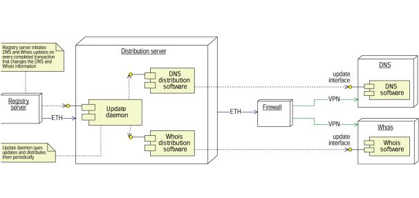
Figure 56: Distribution of the WHOIS data
D15.2.9 System Security
To ensure the security of the entire installation, and protection against loss of data, several methods will be employed, mainly in six areas:
1) Firewalls - State-of-the-art firewalls, Cisco PIX-520, will be employed one the borders of the network
2) Security of production software and hardware - the systems themselves will run stripped versions of Linux, always with the latest security patches applied.
3) Software and hardware encryption of data and transfer channels – the DNS update transfers, the Registry-Registrar interface, and the escrow transfers will be strongly encrypted.
4) Physical security measures on premises - The physical premises will be physically secured from unauthorized access and made to minimize external influence on its operations, even during major external events.
5) Intrusion Detection Systems - a passive system listening to all traffic and all packets on the connected network, which employs an artificial intelligence algorithm to detect traffic and behaviour that deviates from the normal and therefore could mean intrusion.
6) Update procedures – Procedures for updating data both internally and externally are designed to withstand faults such as memory errors or server breakdowns.
The Firewall
The PIX-520 is Cisco's most advanced enterprise firewall, based on a proprietary operating system that not only allows the PIX-520 to handle very high volumes of traffic (up to 250 000 connection per second), but also greatly improves security. It uses an adaptive algorithm for stateful inspection (SI) of the source and destination address, sequence number, port number and flags of the TCP connections.
This design is superior to the traditional packet filtering approach as it eliminates the need for complex filtering rules and allows for higher level decisions.
The external connections (registrar clients, remote DNS servers) will be connected to a PIX-520 firewall equipped with VPN cards providing strong hardware encryption. This VPN tunnel will ensure the clients a tamper proof, secure connection to the main network.
Software and hardware security
The servers will run stripped down versions of Linux, only offering one service each in addition to the remote login service, ssh. This approach will make it simpler to monitor and maintain the systems, and minimize the damage in case of a security breach or other events resulting in system downtime.
The services will use a wide extent of open source software. While statistics show that open source software has more or less the same amount of security problems as proprietary software, security patches are usually available much faster, often within 24 hours. Security staff will daily monitor security related web sites for relevant security problems, and apply patches as soon as they are available.
In cases where especially problematic security problems are found and/or patches does not seem to become available within a reasonable time, the open source software model will allow the staff to be assigned to write/create a patch for assigning our own staff to writing a patch.
All of the systems will be running the secure shell (ssh) service, which utilizes heavily encrypted connections and strong authentication, to provide remote administration capabilities. The ssh service has been the standard secure remote login service for several years, and has no known security problems.
The software that is open source, like BIND, DJBDNS, LINUX will be monitored daily for updates and patches to cover potential security holes and possible malfunctions. It will be a daily task for the system administrator to check the relevant sites for updates to the current software installation.
Software and Hardware Encryption
The PIX Firewall IPSec encryption card, enables the tamper proof, secure communication over the Internet between the Registry main site and the external data centres, as well as between the Registry and the Registrars. The secure VPN tunnel created allows DNS updates and the Registrars’ operations to be done safely and securely.
The regular data transfers to the assigned Escrow Agent, as described in section D15.2.7, will be done over a standard FTP channel. It is vital to ensure that the transferred data are not detected or tampered with, and all transferred data will therefore be encrypted and signed using the asymmetric encryption PGP (Pretty Good Privacy). The receiving Escrow Agent will be the only entity with the appropriate keys and ability to decrypt the data and take it into escrow. The PGP keys, although virtually impossible to crack, will be changed every 6 months to reduce the risk of compromised keys due to human errors.
Intrusion Detection System(IDS) and Intrusion Response Team(IRT)
We will employ an Intrusion Detection System (IDS), with a Intrusion Response Team (IRT), from System Security, a Norwegian company. The IDS is a passive system, listening to all traffic and all packets on the connected network, but sending none. It is therefore virtually impossible to detect the presence of the IDS. The IDS is a learning system which after the initiation period employs an artificial intelligence algorithm to detect traffic and behaviour that deviates from the normal and therefore could mean intrusion. In the case of such an alarm, the Intrusion Response Team will immediately investigate and take the appropriate action.
(In Appendix.D.2.6 is attached is an offer for an IDS solution from System Security AS.)
Physical security of the facilities
It is expected that the hosting subcontracted or otherwise acquired under the agreement with IBM (See Appendix D.2.1.1) have high standards of physical security, strict environment controls and fast Internet connections with high level network availability. The physical security controls are in place around-the-clock and include:
· Controlled access for designated personnel
· Alarm systems
· Video surveillance of public site facilities
Environmental controls in each data centre include:
· Smoke, fire and water leak detection systems
· UPS/CPS power feeds that ensure 99.99% power availability
· Heating, ventilation and air conditioning systems.
For more information on the facilities, see the IBM part of this proposal for this part of the system.
Update procedures
To ensure that data is not lost in the event of a system failure on any part during the updates and that system recovery time is minimized, the following procedure will be applied:
a) Upon reception of an SRRP command, the Rate Controlling Middleware immediately writes the received data to disk, and makes sure it is not only cached by the OS by using the fsync() or fdatasync() system calls.
b) The RCM inserts/updates the data in both the databases. This gives us the possibility to detect errors in one or both of the databases in case the databases do not give identical replies, and allows for a duplication of all the data in case of an error that corrupts the data in one of the databases.
c) After a successful completion of the command, the information will be sent to the update server, which will immediately write the information to a temporary file on the disk. The fsync() or fdatasync() system calls will be applied here also. The information is then deleted from the disk on the RCM.
d) The update server now attempts to update all the WHOIS and DNS servers with this information. The update server will always also maintain complete datasets of the WHOIS and DNS server files, which is also updated at this point. When this has completed successfully, the temporary file will be deleted from the disk of the update server.
Using this procedure, data will be secure:
a) In the case of an unexpected outage on the RCM, operation can be rapidly resumed. In the event of fatal hardware errors, the RCM can be replaced with identical hardware. Once the RCM is restarted, it will go through all the files written to the disk, and check with the database to see if the information was updated successfully. If the information on the hard drive of the RCM differs from the information in the database, the database is authoritative, and the information is deleted from the RCM. This is because this means that the information was not updated, so the registrar client software was never notified that this SRRP operation was successful, and it is the responsibility of the registrar to repeat the operation until he knows that the data has been successfully updated in the registry. If the information on the hard drive of the RCM is identical to the information in the database, this means the SRRP operation was successful, and the data will be committed to the update server. If the system outage on the RCM also resulted in corruption of the filesystem, the entire dataset must be regenerated from the databases.
b) In the case of an unexpected system outage on the update server, operation can also be rapidly resumed. In the event of fatal hardware errors, the update server can also be replaced with identical hardware. Once the update server is restarted, it will go through all the temporary files on its hard drive and update all the WHOIS and DNS servers with this information. If the system outage resulted in a corruption of the filesystem, the entire dataset must be regenerated from the databases.
c) In the case of a failure on the database, the data will be duplicated in the other database. In addition, in case of a complete non-recoverable failure of the ESS, the data will be available from database backup and the complete logs from the SRRP interface, which is also stored offsite.
d) In the case of an error on one of the WHOIS servers open to the public, this computer will be replaced/restored. A complete copy of the current information will be located on the update server, so this can be copied to public whois server, while the update server application will be receiving new updates as usual. When all the information has been copied, the new whois server will be reopened for public access.
e) In the case of an error on one of the DNS servers open to the public, this computer will be replaced/restored. A complete zone transfer will then be done from the primary stealth DNS server, and the DNS may then be reopened for queries from the public.
D15.2.10 PEAK Capacities
Registry service
During the first few hours or days of operation, the demand for registration will probably be several orders of magnitude higher than during normal operation. To avoid overloading the core components of the system, the Registry server and the system configuration around it will deploy a strict round robin algorithm implemented in the IBM product MQ (See Appendix D.2.1.1 for more detail on MQ) for registrars in the event of excessive load.
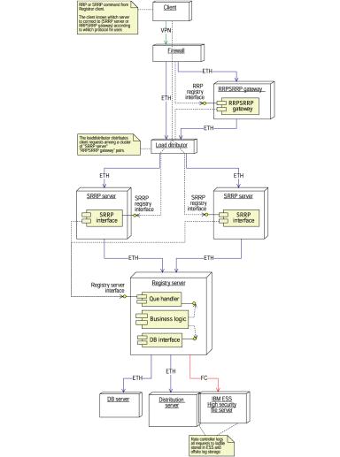
Figure 57: The Registry server is ensuring orderly registrations and load is balanced both in frontend and middleware
This configuration of the system for registrations is designed to give the Registrars a problem free, secure and fair access to registrations.
- The firewall and the VPN cards give security, allowing the Registry and the Registrar to perform transactions with greatly reduced risk of compromisation of sensitive data.
- The load balancer allows the traffic to be equally distributed over several hardware components, reducing the risk of downtime caused by hardware or software failure in the SRRP servers. These hardware components are placed in an active/active configuration, so the capacity for registrations can be increased easily. If there is a peak in traffic that is higher than the Registry can handle in real time, this traffic can be buffered in the SRRP servers until the database is available, given that the peak is not so high that all the SRRP servers are overloaded. If this is the case, more SRRP servers can easily be added.
- Transactions from the SRRP servers are passed along and queued on the Registry server in a controlled manner, making sure that the Registry server is never overloaded. The Registry server queues these also, but now with one queue per Registrar. The transactions will be chosen from each queue in a round robin fashion, skipping empty queues. This is a method that makes the number of transactions in the database per Registrar fair, in periods of high load.
Each of the components of the Registry frontends and backends are scalable.
- The frontends, or SRRP servers, are scalable by adding more components to the active/active configuration.
- The backend, or Registry server, can be scaled with the frontends. Although it has not been shown in the hardware diagram, it would be possible to add another Registry server, so that each Registry server is connected to half of the frontends, and since load is equally balanced between the frontends, it follows that load will be more or less equally balanced on the various Registry servers. More Registry servers can be added in a similar fashion.
- Running parallel versions of the databases can scale the databases up.
- The update server can be scaled by spreading updates of DNS and WHOIS to separate machines, and if this is not enough, one can set dedicated update machines for groups of WHOIS and DNS servers.
- The inhouse WHOIS and DNS servers are scalable by being located in an active/active configuration like the SRRP servers, and more may be added when necessary. Also, more DNS and WHOIS servers can be placed in the external locations, so that load can be spread.
This will ensure that the initial registration rush does not overload the core system, and that registrations are handled in a fair way when the demand is above the threshold specified in the Registry server. ie. if registrar 1 (R1) submits 2 registrations immediately followed by registrar 2 (R2) who submits 10, and the Registry server is above the safe threshold, R1 will be granted 1 registration, then 1 for R2, then one for R1 and finally the rest of the requests from R2 will be processed.
In addition to protecting core systems and ensuring a certain amount of fairness during periods of very high demand, the Registry server will also improve the user interaction of the registration system, as users will get an error message instead of connection refused or similar if their operation cannot be carried out because of too high demand.
DNS service
The DNS service will not have any special measures for handling very large load. Instead, a combination of the distributed nature of DNS, over sizing of the DNS servers and rigid monitoring of the server loads will ensure that the service remains operational.
Normally the in house DNS servers will have a lot of spare capacity and only hostile actions, such as traffic caused by a distributed denial of service (DDoS) attack would cause the servers to become saturated. In case of a DDoS attack, the monitoring software would alert an administrator in a matter of minutes after the attack is launched, and the attack would be stopped to re-establish normal operation.
D15.2.11 System Reliability
In
defining the reliability of the system we are defining strict goals that we do
not want to stretch, and soft goals that we allow not to be fulfilled
completely. Several of the high level goals may seem obvious, but it is
important to realize that the completion of these goals is not
straight-forward. Significant effort has been deployed to make sure that
reliability is maximized in all areas within the possible and that the
following conditions can be met:
·
Registered
domains will not disappear.
·
Once a
registration has been confirmed to the Registrar, the domain name is
registered.
·
All
domain names in the DNS servers will be properly registered domain names.
·
All
domain names in the WHOIS servers will be properly registered domain names.
·
A
properly registered domain name will after updates be in the DNS servers.
·
A
properly registered domain name will after updates be in the WHOIS servers.
·
The
database of registrations can be fully restored even in the case of a partial
of full destruction of the main data center, with the possible loss of the last
domain name in case of a full destruction.
Factors
that contribute to guaranteeing the reliability of the system:
·
The
WWW, WHOIS, database and DNS hardware are running in a high availability
active/active failover configuration, running RAID5 with the ESS in addition
being internally mirrored. The database is running separately on two machines,
the DNS is distributed, the backup is taken once a day and goes offsite and the
log is distributed offsite in real time.
·
There
will be alarms for malfunctions on all critical systems, including the DNS,
update machines and Registration servers.
·
The
DNS is the only real critical element, and although each single DNS server
cannot guarantee a 100% uptime, multiple servers are replicated on different
networks, making a 100% uptime possible.
99.8% uptime can be expected on the registrar systems and www, as this
is the uptime the mother company Nameplanet.com is currently achieving on its registration
services, web mail and other Internet services. Scheduled downtime, periodic
updates or otherwise downtime not critical to the stability of the DNS is to be
expected.
·
The
database and all related elements are backed up while running.
·
The
DNS updates, WHOIS updates and WWW updates are done while the system is
running.
·
Most
of the machines are diskless, and can be easily replaced in case of failure.
All these machines will boot from the ESS.
·
We are
using high-availability servers and the most critical ones are running well
proven operating systems and hardware (8000 on AIX/IBM RS)
·
There
will be a stock of hard-drives and vital servers in case of crashes. All
servers boot from ESS.
·
The
software and hardware will be continuously monitored for updates and publicly
announced security holes, and will be updated at the earliest point. (ref to
D15.2.7).
·
Passwords
will be updated in the VPN interface, thus making forgery difficult.
D15.2.12. System outage prevention
Procedures for problem detection, redundancy of all
systems, back up power supply, facility security, technical security,
availability of back up software, operating system, and hardware, system
monitoring, technical maintenance staff, server locations.
The system outage prevention has the following elements:
· Daily backups transported offsite
There will always be a backup available less than 24 hours old, on tape. The backup robot stores the entire ESS, that is all registry data, configurations and partitions of the servers in the centre to tape, which is transported offsite daily by a security firm dedicated to this service for the co-location centre. The tapes are then stored in magnetically shielded vaults away from the site.
· 24/7 availability of technical maintenance staff, on alert, green-light management.
There will be staff on site, for green-light management, monitoring the servers and checking that they do not go down. In case they do, the staff will restart the servers and alert the technical team if necessary.
· Doubled, redundant database servers and database storage
As described in D15.2.3 the database is duplicated on two different IBM R/8000 6 way M80 servers running AIX, and the data is stored on the ESS, which is also internally mirrored, running RAID5 on each part. This double duplicity gives extended security. The fact of having two databases with the exact same data ensures that one database may write the wrong data to the database, in case of internal errors, software errors or hardware errors like memory faults. Such errors, although extremely unlikely, can then be detected and corrected by the technical personell. If one database server crashes, the registrations can continue if so chosen, although without error correction of this type.
· Mirrored, backed up storage for all data and software
The ESS is an internally mirrored, RAID5 controlled system which is backed up regularly. The internal mirroring ensures that the entire RAID5 array of disks on one side can break down and it will still retain full functionality. Full breakdown of the ESS is extremely unlikely unless in the case of fire. (Fire prevention systems are obviously in use in the colocation centre). The ESS can also as a future addition be mirrored via a dedicated fibre link to an external centre, over a distance up to 100km. This would effectively double the already double storage security. See Appendix.D.2.1.3, Appendix.D.2.1.4 and Appendix.D.2.1.5 for more information about the IBM ESS.
· Continuous log of database transactions transported offsite
All transactions editing or updating the database will be logged and the log will be continously be sent to an external datacentre over an encrypted link. In case of breakdowns where the internal log is corrupted, the external log can be retrieved.
· Hardware encrypted communications with Registrars and external DNS servers
All communication of critical data to external sites, both Registrars, DNS sites and the Escrow agent is strongly encrypted and protected against eavesdropping and/or decryption.
· Top class enterprise firewalls PIX 520 in failover configuration.
The PIX 520 firewall is Cisco’s most advanced enterprise firewall and will be operating in a active/passive failover configuration. In case one goes down, the second will take over immidiately.
· High availability active/active failover system on critical systems
Both firewalls, Registrar interface servers, web-servers, DNS servers, WHOIS servers and database servers are operating in high-availability active/active failover system.
· Servers and hard disks in stock, pre-configured and ready to boot from the central storage ESS
There will be servers in stock, configured to boot from the right partition of the ESS, that can be put in as replacement for servers where hardware error occurs, or where the reason for failure is not established or known. They can also be installed in the active/active failover configurations to scale for higher load if needed. In addition to extra servers, there will also be numerous hard drives that can be hot-swapped with drives in the RAID configuration, when hard drives fail. This will ensure continous operations in case of hardware failure.
· Continuous monitoring of services and mobile alarm functions in case of malfunction
The load on registrations in particular, as well as other services, will be continuously automatically monitored and in the case of high load, congestion, crashes or other risk situations, the relevant staff will be alerted via email and SMS, at all hours. This will ensure that appropriate measures are taken if the failover systems or others are at risk.
· Power supply backup and UPS
The colocation has a power supply backup in case of power outages. There will also be connected a UPS, which will not allow for continuous operations in case the power supply backup also fails, but the UPS will allow the whole system a graceful shutdown, so it can be rapidly taken up again when the power supply returns.
· Facility security including access control, environmental control, magnetic shielding and surveillance.
A physical security system to prevent unauthorised person(s) from obtaining physical access to the premises or the equipment on site should be in place. As a minimum this should consist of access control equipment, intrusion detection equipment and CCTV surveillance equipment as well as having 24-hour security staff on the premises.
Air conditioning is be provided in the co-location centre with N+1 redundancy and be capable of maintaining the environmental temperature at 20°C ± 5°C and humidity between 20% and 65% suitable for server equipment.
The physical environment is monitored 24 hours a day. These systems check a full range of environmental factors including, temperature, humidity, power, security systems, water detection etc. If any system is found to be operating outside normal working parameters, the on-site staff will investigate and arrange for the appropriate service or maintenance work to be carried out.
A fully automatic fire detection and alarm system that is linked to automatic suppression systems is required, with the suppression system based on Argonite (or similar).
· DNS servers on different backbones, and with software diversification, running two different versions of resolution software at all times.
The most critical element of the Registry operations is the DNS servers ensuring stable operations of the registered domain names all across the world. The DNS servers are multiplied in failover systems, spread across different backbones and will in addition be diversified through the software they run. While BIND is a very proven software, some servers will run other applications for DNS resolution, namely DJBDNS, which is developed by a different group than BIND and possess different characteristics. It in unlikely that an error affecting all BIND servers, i.e. security holes, should also affect the DJBDNS software, thus allowing the DNS resolution to remain active even in the case of full BIND breakdown.
· The critical elements run extremely proven hardware, AIX on IBM M80 is one of most proven configurations in the industry
Proven, high performing hardware and software will be used for the most critical elements, the database in particular. Both operating system, hardware and database software is made by the same vendor, IBM, and has been proven through numerous installations in other transaction based industries, like banks. The same system will run the registrations in the Global Name Registry.
· A committed, stable and extremely experienced technological partner for the Registry, IBM.
The most important partner in the Global Name Registry proposal to ICANN is IBM, which will provide the elements in which IBM’s unique competence can be fully utilised. The partner’s commitment ensures stability of the operations.
· Passive intrusion detection (IDS) with artificial intelligence surveys the network for “unusual” traffic.
The IDS system is a learning system which monitors all traffic on the internal network. It is capable of detecting “unusual” traffic patterns, which could mean intrusion attempts, fraud, or otherwise behaviour in the system and communications that are not standard. The IDS would alert in case of suspicion and the potential problem can be corrected or intrusion deferred.
· Focus on top class hardware, standardized on few different products from solid vendors, IBM and Cisco.
By focusing the hardware to certain well-proven series, the Global Name Registry will operate a minimum of different hardware making it easier to maintain, replace, install, upgrade and secure. Top class suppliers have been chosen to provide the best of breed.
· Proven software and operating systems, open source software used where appropriate.
Open source software is running much of the Internet infrastructure today, and well proven open source software is used wherever appropriate. As an example, Linux will be used in the front-end web servers because of the level of control it is possible to have over it’s functionality. This is extremely useful in case of intrusion attempts, DdoS attacks (change in TCP layers), but also during normal operations, since it is well known with much competence available. The DNS software, BIND and DJBDNS is also opensource, as is Apache, the web server. This software is continuously updated and improved, and is among the safest available.
· Drawing experience from key personnel on web operations and DNS operations.
The mother company Nameplanet.com has gained valuable experience in web operations and DNS operations that will be transferred into GNR.
D15.2.13 System recovery procedures
Fast recovery in case of single server failure
To ensure that data is not lost in the event of a system failure on any part during the updates and that system recovery time is minimized, the following procedure will be applied:
e) Upon reception of an SRRP command, the Rate Controlling Middleware immediately writes the received data to disk, and makes sure it is not only cached by the OS by using the fsync() or fdatasync() system calls.
f) The RCM inserts/updates the data in both databases. This gives us the possibility to detect errors in one or both of the databases in case the databases do not give identical replies, and allows for a duplication of all the data in case of an error that corrupts the data in one of the databases.
g) After a successful completion of the command, the information will be sent to the update server, which will immediately write the information to a temporary file on the disk. The fsync() or fdatasync() system calls will also be applied here. The information is then deleted from the disk on the RCM.
h) The update server now attempts to update all the WHOIS and DNS servers with this information. The update server will always maintain complete datasets of the WHOIS and DNS server files, which is also updated at this point. When this is successfully completed, the temporary file will be deleted from the disk of the update server.
Using this procedure, data will be secure:
f) In case of an unexpected outage on the RCM, operations can be rapidly resumed. In the event of fatal hardware errors, the RCM can be replaced with identical hardware. Once the RCM is restarted, it will go through all the files written to the disk, and check with the database to see whether the information was updated successfully. If the information on the hard drive of the RCM differs from the information in the database, the database is authoritative, and the information is deleted from the RCM. This means that the information was not updated so the registrar client software was never notified that this SRRP operation was successful, and it is the responsibility of the registrar to repeat the operation until he knows that the data has been successfully updated in the registry. If the information on the hard drive of the RCM is identical to the information in the database, this means that the SRRP operation was successful, and the data will be transferred to the update server. If the system outage on the RCM also resulted in corruption of the filesystems, the entire dataset must be regenerated from the databases.
g) In case of an unexpected system outage on the update server, operation can also be rapidly resumed. In the event of fatal hardware errors, the update server can also be replaced with identical hardware. Once the update server is restarted, it will go through all the temporary files on its hard drive and update all the WHOIS and DNS servers with this information. If the system outage resulted in a corruption of the filesystem, the entire dataset must be regenerated from the databases.
h) In case of a failure on the database, the data will be duplicated in the other database. In addition, in case of a complete non-recoverable failure of the ESS, the data will be available from database backup and the complete logs from the SRRP interface, which is also stored offsite.
i) In case of an error on one of the WHOIS servers open to the public, this computer will be replaced/restored. A complete copy of the current information will be located on the update server, so this can be copied to a public whois server, while the update server application receives new updates as usual. When all the information has been copied, the new whois server will be reopened for public access.
j) In case of an error on one of the DNS servers open to the public, this computer will be replaced/restored. A complete zone transfer will then be done from the primary stealth DNS server, and the DNS may then be reopened for queries from the public.
The extremely unlikely scenarios that will give a complete loss of some data internally (because there is always the offsite backup) are the following:
a) The ESS breaks, and the offsite log of the SRRP breaks, both beyond recovery, at the same time, before the updates are distributed to the WHOIS and DNS servers.
b) Both database servers break data beyond recovery, and both the onsite and offsite log of the SRRP break, all at the same time, before the updates are distributed to the WHOIS and DNS servers
Recovery in case of full or partial data center destruction
In the
unlikely event of the whole data-center being destroyed, by fire, bombing,
earth quakes or other force majeure that could impact the strongly protected
data center severely (ref. also section on the hosting environment which is
extremely protected), the system can still be recovered.
It is
notable that in all events except for a full internet breakdown or full
destruction of all production centers and external DNS centers, the operation
of the DNS and the WHOIS would go on normally, but new registrations and
updates to the DNS records would be halted in the case of major destructions in
the main data center.
It is
highly unlikely that an event would occur so as to destroy the hosting center
or otherwise render the database system inaccessible through full destruction.
Such an event as a nuclear attack, major earthquake or similar would have
other, and more severe impacts on the society than the unavailability of new
registrations. The DNS would in such a case still be up.
In case
of an ESS breakdown, where both of the internally mirrored storage areas of the
ESS are destroyed, the following procedure would be deployed:
·
An
analysis of the reasons why the ESS broke down would be conducted.
·
The
ESS would be replaced with another identical ESS, or a similar storage facility
·
The
backup that has been taken offsite would be returned and restored onto the
storage
·
All
servers could be rebooted from the central storage where each of the partitions
would then be remounted
·
The
offsite log of the transactions done between the last backup and the breakdown
would be restored and retraced, resulting in a data collection identical to the
one immediately before breakdown.
·
The
systems would be tested and consistency checked on the internal and external
DNS and WHOIS servers, which would remain up during the whole procedure.
·
The
full service would be reopened.
In case
of a full data center destruction, a similar procedure would be followed, with
the exception that a full or at least partial server park would need to be
acquired from the supplier. The supplier would, with reference to service level
agreements, be obliged to supply the minimum hardware needed.
·
Relocate
the service to a new data center (assuming full destruction of the previous)
·
Install
new hardware
·
Return
the backup that has been taken offsite and restore it onto the storage
·
All
servers could be rebooted from the central storage where each of the partitions
now would be remounted
·
The
offsite log of the transactions done between the last backup and the breakdown
would be restored and retraced, resulting in a data collection identical to the
one immediately before breakdown
·
The
systems would be tested and consistency checked on the internal and external
DNS and WHOIS servers, which would remain up during the whole procedure
·
The
full service would be reopened
D15.2.14. Technical and other support.
The key account team will handle support for Registrars and the Support Team will be assigned complimentary responsibilities. The Key Account Managers will mainly handle pre-sales, although they will keep the primary relationship with the Registrar and will be available also for other matters. The Support Team will handle post-sales requests when a Registrar is in operation, as well as requests from general Internet users.
Every Registrar will have the possibility to contact the Registry via email or telephone to request assistance in matters like technical implementation, registration status, credit increase, billing status, etc.
The Support Team will be using the Ejournal request management system, a system for managing large amounts of requests. The main focus of the system is handling email to non-personal accounts such as support@company.com or sales@company.com, however, the system is also capable of handling phone requests, internal todo documents and other tasks that need to be tracked. The system offers several tools, both automatic and interactive, which help meeting the following overall goals:
a) Minimizing the time spent replying or managing each request.
b) Guaranteeing that no request is left unanswered.
c) Offering full control over incoming and outgoing communication. This includes:
i) Detailed information for each request, including exact timestamps, detailed logging and complete listing of messages.
ii) Flexible reports and statistics, offering an overview of all requests being handled.
(A description of the Ejournal RCM system is attached in Appendix.D.2.4)
Personnel will be accessible within business hours in the location they work from, extended so as to provide for a telephone support window for all time zones. For some time zones, however, email support will be the preferred solution and can be just as efficient.
The Registrars will additionally have access to a web-based information system running on SSL, where they can access information regarding registered domains, nameservers, billing status, etc. The web interface will provide information only, and cannot be used for critical and sensitive tasks such as changing passwords, registering domains etc, for which the VPN interface will be used instead.
Key Account will initially be available in English only, given the general nature of the contracts the Registrar is entering into during the ICANN Accreditation and the initial Registry relationship. However, it is expected that as the number of Registrars grows all across the world, new languages may become available thanks to the recruitment of new Key Account Managers with different language skills for the purpose of a closer relationship to the Registrar. The general Support Team will initially be giving support in 7 languages - English, Spanish, French, German, Swedish, Norwegian and Danish - outsourced from Nameplanet.com, the mother company. It is a goal for the Global Name Registry to have good language support for the requests it is receiving.
As a general rule, most support requests from Registrants will be referred to the corresponding Registrar.
The Registry will mainly be dealing with transfer requests from Registrants, witch involves contact with the Registrars. However, the Registrants domain password can be made available from the Registry if the Registrant chooses to get it in that way.