Locations of Systems
Registry services for critical elements of the Internet infrastructure must
be housed in world-class facilities. The UIA team will operate the .org TLD from
VeriSign's three major Internet data centers in the continental United States,
from which it currently provides numerous critical Internet services, including:
- Management of the Internet root zone and operation of 2 of the 13 Internet
root servers (a.root and j.root)
- Management of the .com, .net and .org registries
- PKI certificate authentication
- Trusted payment services
Additionally, the UIA Team has partnerships with major collocation facilities
throughout the United States, Europe and Asia that provide increased reliability
and redundancy for critical Internet services (e.g., nameserver resolution).
These partner facilities must conform to rigorous standards and are subjected to
a detailed physical inspection prior to being selected. The locations of the
data centers and the partner collocation centers are depicted in Figure C17.1-1.

| Broad Run Internet Data Center |
Sterling, Virginia |
| Lakeside II Internet Data Center |
Dulles, Virginia |
| Mountain View Internet Data Center |
Mountain View, California |
| AOL Data Center |
Ashburn, Virginia |
| Internap Collocation Center |
Atlanta, Georgia |
| Terremark Collocation Center (NAP of the Americas) |
Miami, Florida |
| Internap Collocation Center |
Seattle, Washington |
| AOL Data Center |
Sunnyvale, California |
| Internap Collocation Center |
Los Angeles, California |
| TeleHouse Collocation Center |
London, United Kingdom |
| NIC/SE Data Center |
Stockholm, Sweden |
| Global Switch Collocation Center |
Amsterdam, Netherlands |
| KDDI Data Center |
Tokyo, Japan |
| PCCW Data Center |
Hong Kong, China |
Figure C17.1-1: Data Centers and Partner Collocation Centers
Global resolution sites are critical for a TLD that has a global focus. The
reliability and stability of any global TLD dictates that DNS responses be given
as quickly as possible and as close to the point where the query is issued.
Each data center has the following features:
- 7x24 onsite Network Operations Center (NOC)
- Redundant UPS
- Redundant generators
- Redundant Power Distribution Units (PDUs) with redundant circuits to each
equipment rack
- Redundant fire suppression (FM200 gas as primary with dry-pipe
individually activated sprinkler heads as back-up)
- N+1 cooling and humidification
Despite the features designed into a single facility, no single facility can
be depended upon for 100% reliability. For that reason, two of the major data
centers house sufficient equipment to independently operate the .org registry.
Additionally, the Lakeside II data center is designed as two data centers in
one, with separate infrastructure and security. This design, coupled with the
ability to load-balance and/or shift services between facilities, provides for
the most robust facilities infrastructure imaginable for the .org registry.
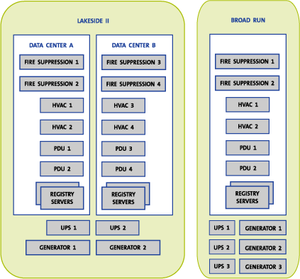
In this architecture (depicted in Figure C17.1-2), registry services are
load-balanced between data center A and data center B at the Lakeside II
facility and also between the Lakeside II and Broad Run facilities.

Figure C17.1-2: Data Center Redundancy
This architecture offers maximum protection and reliability for registry
provisioning services. The secondary data center is located several miles away
from the primary data center rather than across the country. This separation has
three distinct advantages:
- Critical data can be synchronized in real time from the primary facility
to the secondary facility. Such synchronization is not possible with
facilities located across the country.
- The most technically qualified personnel are more easily and more quickly
able to perform recovery services if the recovery site is a reasonable
distance away and does not require either a trip by plane or the hiring and
training of personnel at the secondary site.
- Production RRP traffic can be load-balanced between sites as a normal mode
of operation. Load balancing provides extra capacity as well has a high
degree of confidence (in addition to formal testing) that the secondary site
would be able to quickly assume all functions if a major event disabled the
entire primary site.
Internet DNS is, by its very nature, quite robust, but this is no excuse not
to invest in and implement additional DNS functions designed to improve DNS
reliability and security. Each nameserver resolution site around the globe must
adhere to strict facility standards. Beyond this, however, operational processes
and procedures have been developed so that DNS services can be quickly moved
from one site to another. A DNS "swing" site will continue to be maintained at the
Lakeside II data center where DNS traffic from any of the 13 resolution sites
can be quickly redirected. The swing site is a major element of the business
continuity plan and will be used to support site maintenance.
Types of Systems
The hardware systems that the UIA Team will use for the .org registry have
been extensively tested and validated in a state-of-the-practice engineering
lab. IBM enterprise servers (e.g., S80 and P680 models) running the AIX
operating system perform as database servers. Oracle is the DBMS used as the
database. Application and gateway servers are a mixture of IBM and Linux
servers. Web and FTP servers are a combination of IBM, Linux and Sun servers.
Cisco, Foundry and Alteon provide network and load-balancing equipment.
The server functions will be protected with hot stand-by servers, using IBM HACMP
for automated failover monitoring and execution. The data itself will be housed on
EMC Symmetrix equipment and will be synchronized in real time to multiple secondary
EMC Symmetrix devices located in multiple data center facilities. This
architecture will be capable of processing more than 300,000 transactions per minute
and operates at reliability rates of better than 99.9%. More details of the
demonstrated capacity and reliability of this architecture are discussed in
Section C17.3.
It is contrary to security policy to publish the architecture or capacity of
the global DNS constellation because of its criticality to the stable operation
of the Internet and because it is often a target of Internet
"hackers". However, that architecture does utilize redundant hardware
systems with no single points of failure. It currently handles more than 90K
queries per second on a regular basis and has successfully handled peaks of
nearly 400K queries per second.
Facility Infrastructure
A facility must be judged by the robustness and reliability of the
infrastructure that supports elements such as electrical power, cooling,
humidity and fire suppression. Data center facilities proposed for use by the
UIA Team are designed to provide a redundant electrical infrastructure all the
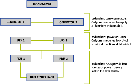
way to the individual racks in the data center. As an example, Figure C17.1-3
shows the electrical infrastructure design of the Lakeside II facility.

Figure C17.1-3: Electrical Infrastructure
With this design, there are no single points of failure. Since most I/T
equipment today is outfitted with dual electrical connections and dual power
supplies, each component of the electrical infrastructure, from the street to
the CPU, is fully redundant. Redundancy also supports scheduled maintenance. The
electrical infrastructure is designed to continue to provide service in the
event of a failure or planned shutdown of any component.
Each data center HVAC and humidity control system is designed to a minimum of
N+2 redundancy. This means that two HVAC and/or humidifier units could fail (or
be taken down for maintenance), and still provide proper cooling and humidity.
Temperature is maintained at 70 degrees Fahrenheit with a variance of plus/minus
3 degrees. Humidity is maintained at 50% with a variance of plus/minus 5%.
Primary fire suppression is provided by FM200 gas with individually activated
sprinkler heads as secondary. The sprinkler system is "dry pipe,"
which means that compressed air keeps water out of the overhead pipes in the
data center to avoid the risk of water leaks damaging equipment. In the event of
an FM200 discharge, all power to the data center would be turned off. However,
the FM200 will not damage equipment, and a data center equipped with FM200 can
be back up and running following a discharge as soon as the reason for the
discharge is identified and fixed. No equipment cleanup is required.
Data Center Design
At the primary data center facility, an extra step has been taken by
designing two separate data centers in one facility. Each data center has its
own electrical infrastructure, HVAC, humidity control, and fire suppression.
This design provides three distinct advantages. First, redundant system
architectures that might not normally be distributed across geographically
separate facilities can be distributed between two data centers that have
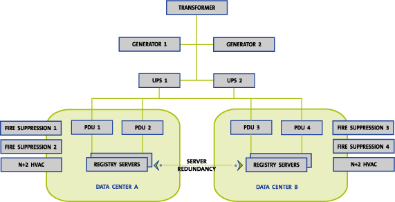
completely separate supporting infrastructures. Figure C17.1-4 shows this
architecture as it applies to the .org registry equipment.

Figure C17.1-4: Redundant Data Centers within a Single
Facility
The second advantage is that although production is distributed between both
data centers, development and test equipment is kept in only one. Therefore, one
data center will be dedicated solely to production equipment and services. There
will be less activity in this data center, making it less susceptible to
"collateral damage" that can occur as a result of changes. Finally,
different levels of physical security will be applied to each data center,
ensuring that staff having access to development and test systems are not able
to access the data center that is dedicated to production services.
Server Architecture
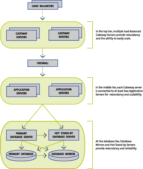
The UIA Team will use a three-tiered architecture for the .org registry as
shown in Figure C17.1-5. Technologies applicable to each tier will be used to
provide redundancy at each tier. For example, at the database tier, the EMC SRDF
product will be used to replicate data in real time to multiple locations, both
inside the data center (e.g., between multiple data centers in the same
facility) and to the secondary data center. Additionally, hot stand-by servers
with automated failover using IBM's HACMP function provide for redundancy of the
database server. Load-balancing the transactions across multiple gateway servers
and application servers will provide reliability and redundancy in the other tiers.

C17.1-5: Redundancy at Each Server Tier
Software Systems
Software systems include more than just the products used and their design.
They also include the process by which the software was designed, developed,
tested, and deployed. As shown in the previous section, the proposed .org
registry is designed in a three-tiered architecture. This structure separates
gateway functions (e.g., login, session management, service auditing),
application functions (e.g., business rules) and database functions. In doing
so, security will be improved, problems more easily diagnosed, and modifications
more easily and reliably tested and deployed. Standard industry software
products (e.g., Java, C, and C++) will be utilized as appropriate at each tier to
facilitate performance and compatibility. WebLogic will be used for web application
server development. A rigorous quality assurance and testing methodology will be
utilized that includes a separate, fully functional, production "look
alike" environment where new software can be tested prior to deployment.
Additionally, a "staging" environment enables deployments to be
practiced repeatedly to ensure that they can be executed seamlessly within
maintenance windows. The staging environment also enables an accurate prediction
of the length of a deployment and back-out plan, if necessary.
Level of Security
If natural disasters weren't enough of a risk, in this post 11 September age,
no one doubts that physical facilities present the most obvious target for
terrorist activities. The data center facilities of the UIA Team possess the
most obvious characteristics of security, including:
- Low profile (e.g., no external markings or signage)
- Hardened against regional weather events (e.g., high winds or hurricanes)
- Located outside of flood areas
- Multi-level physical security, including 7x24 onsite security force, badge
readers and biometric access control devices
- 7x24 video surveillance
A dedicated I/T security team provides for logical (or I/T) security. This
dedicated team will be responsible for the development and implementation of security
standards, the management of security devices (e.g., firewalls), security
monitoring, audits and tests (including third-party penetration tests) and
working within government and industry I/T security forums. The characteristics
of the proposed I/T security functions are outlined in greater detail in Section
C17.9.
Internet Connectivity
Internet connectivity is a critical element for any facility supporting
registry and global DNS functions. Sufficient bandwidth is the primary defense
against Denial of Service (DOS) and Distributed Denial of Service (DDOS)
attacks. Internet connectivity is provisioned through multiple providers and
through multiple physical routes. The Lakeside II and Broad Run data centers
have multiple DS-3 and OC-3 connections to the Internet provisioned through
diverse providers. At data center facilities, redundant Internet connections
enter the facility through diverse cable conduits, travel to the border routers
via separate conduits within the facility and terminate at border routers
positioned in separate cabinets located in different sections of the data
center. Nameservers positioned with collocation partners have a minimum of
diverse 100mb connections. "Super" sites have diverse 1gb connections.
Although currently only one "super" site exists, three more are
planned by the end of 2002. Currently, five OC3s connect the primary and
secondary data centers. They will soon be replaced by dark fiber. As Figure
C17.1-6 also shows, OC48 fiber has been run and is ready to be "lit"
if needed.

Figure C17.1-6: VGRS Data Center Network Connectivity
The data center facilities proposed by UIA and the facilities of its
collocation partners provide the secure underlying physical infrastructure
required to support a growing critical Internet infrastructure at a time when
external attacks (both physical and logical, malicious and non-malicious) are an
ever-growing reality. All facilities are available for inspection by ICANN.


