III.2� Technical Plan For The Proposed Registry Operations (RFP Section 15.2)
JVTeam�s proposed technical solution for registry operations meets ICANN�s (and Internet users�) requirements for a new TLD as follows:�
Introducing Competition�JVTeam will develop and deploy a new, streamlined registry-registrar protocol: the extensible registry protocol (XRP). The XRP provides more features and functionality than the existing registry/registrar interface, and far greater security. The benefits to the Internet community are greatly improved Internet stability and increased public confidence.� JVTeam will work with the Internet Engineering Task Force (IETF) to bring the protocol to standard status.
Improving Registry Reliability�JVTeam will implement co-active data centers and a number of nameserver data centers to create a resilient infrastructure protected against outages through redundancy, fault tolerance, and geographic dispersion. The benefits to the Internet community are improved registry availability and better access to DNS services.
Providing Real-Time Responsiveness�JVTeam will implement near-real-time updates to the zone files and the Whois database. The benefit to the Internet community is the elimination of delay-caused confusion over domain name registrations.
Eliminating Bottlenecks�JVTeam�s high-availability cluster architecture provides scalable processing throughput, dynamic load balancing between the two data centers, and multiple high-speed Internet connections. The benefit to the Internet registrar community is the elimination of registry bottlenecks.
JVTeam�s proposed TLD technical solution is based on our experience with the Number Portability Registration Center (NPRC) and with .com.au registry operations.� Our technical solution consists of co-active registry data centers and nameserver data centers, geographically dispersed to provide protection against natural and man-made disasters.� Section III.2.1 provides an overview of our proposed facilities and systems; subsequent sections expand this overview into a comprehensive technical plan for registry operations.
III.2.1�������� General Description Of Proposed Facilities And Systems (RFP Section D15.2.1)
JVTeam proposes world-class redundant Shared
Registration System (SRS) Data Centers in Sterling, Virginia and Chicago,
Illinois and four nameserver sites in Phase I that will provide the facilities
and infrastructure to host the new TLD Registry. Our facility locations were
selected to give wide geographic separation and provide resilience against
natural and man-made disaster scenarios. The benefit to ICANN and the Internet
community is reliable non-stop TLD registry operations.
ICANN�s priorities for the new TLD registries are to provide a world-class level of services that preserve both the stability of the Internet and the security and reliability of the existing domain name system. JVTeam has developed a fault tolerant architectures including redundant facility implementation, high availability cluster server architectures, fault tolerant database technology, and redundant alternate routed network connectivity supports mission critical service availability now. The Internet community needs to be able to depend on the Internet as a stable, highly available infrastructure for worldwide collaboration and commerce.
In the subsection that follows we describe where the JVTeam facilities are located and provide a functional description and physical description of the Shared Registration System (SRS) data center and the nameserver sites. In subsequent subsections we provide a detailed system description of each of the systems residing within these facilities.
II.2.1.1������ Registry Facilities Site Description
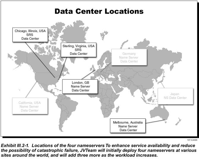
This section describes JVTeam�s proposed TLD Registry architecture consisting of redundant SRS data centers and multiple nameserver sites to provide a seamless, responsive, and reliable registry service to registrars and Internet users. As shown in Exhibit III.2-1 our TLD registry redundant SRS and nameserver data center sites are geographically dispersed worldwide and interconnected with a Virtual Private Network (VPN) to provide worldwide coverage and protect against natural and man-made disasters and other contingencies. The facility locations are provided in the following table.
|
Site Name |
Site Address |
|
Four Data Centers in Phase I |
|
|
JVTeam SRS Data Center and nameserver Site |
200 South Wacker, Suite 3400 |
|
JVTeam SRS Data Center and nameserver Site |
45980 Center Oak Plaza |
|
JVTeam nameserver Site |
Melbourne |
|
JV Team nameserver Site |
London |
|
Planned Data Centers for Phase II |
|
|
JVTeam
Nameserver Site |
Japan |
|
JVTeam
Nameserver Site |
California |
|
JVTeam
Nameserver Site |
Germany |
Our proposed TLD Registry Service Level Agreement (SLA) provides service levels commensurate with mission critical services for availability, outages, response time, and disaster recovery.� Highlights of the SLA include:
� SRS Service Availability is guaranteed at 99.95%, with a design goal of 99.99% per year.
� Nameserver Service Availability is guaranteed at 99.999%
III.2.1.1.1���� Shared Registration System (SRS) Data Center Functional Description
High availability registry services can only be provided from facilities that have been designed and built specifically for such a critical operation.� The JVTeam SRS data centers incorporate redundant uninterruptible power supplies; high-capacity heating, ventilation, and air conditioning; fire suppression; physical security; C2 level information system security; firewalls with intrusion detection; redundant, high availability cluster technology; and redundant network and telecommunications architectures.� When selecting the sites, we considered their inherent resistance to natural and man-made disasters. The functional block diagram of our SRS data center is depicted in Exhibit III.2-2. As can be seen from the referenced exhibit the registry SRS data center is highly redundant and designed for no single point of failure.

Each SRS data center facility provides the functions listed in the system
function directory table below. Descriptions of the SRS systems providing these
functions are provided in the next subsection.
|
�SHARED REGISTRATION SYSTEM (SRS) FUNCTION DIRECTORY |
|
|
System Function |
Functional Description |
|
Web Server |
High capacity Web
Servers provide secure web services and information dissemination that is
outside the scope of the XRP protocol. It contains a registry home page to
enable registrars to sign in and inquire about account status, get downloads
and whitepapers, access frequently asked questions, obtain self help support,
or submit a trouble ticket to the TLD Registry Help Desk. |
|
Protocol (XRP) Servers |
XRP transactions
received from registrars undergo front-end processing by the XRP server that
manages the XRP session level dialog, performs session level security
processing, and strips out transaction records. These XRP transaction records
are sent to the SRS data center application server cluster for security authentication
and business logic processing. |
|
Application Servers |
Processing of the
XRP applications business logic, user authentication, posting of inserts, deletes,
updates to the master database, and interfaces to authentication, billing and
collections, backup, and system/network administration. |
|
SRS Database Servers |
The SRS database
maintains registry data in a multi-threaded, multi-session database for building
data-driven publish and subscribe event notifications and replication to
downstream data marts such as the Whois, Zone, and Billing and Collection services. |
|
Whois Distribution Database |
The Whois
Distribution Database is dynamically updated from the SRS database and
propagates the information to the Whois Database clusters.� |
|
Whois Database Clusters |
The Whois Database
is dynamically updated from the Whois Distribution Database and sits behind
the Whois Server clusters.� The Whois
Database clusters are used to lookup records that are not cached by the Whois
Servers. |
|
Whois Servers |
The Load Balanced
Whois Server Clusters receive a high volume of queries from Registrants and
Internet users. The Whois service returns information about Registrars,
domain names, nameservers, IP addresses, and the associated contacts. |
|
Zone Distribution Database |
The Zone
Distribution Database is dynamically updated from the registry SRS database
and propagated to the nameserver sites located worldwide. It contains domain
names, their associated nameserver names, and the IP addresses for those
nameservers. |
|
Billing and Collection |
A commercial off
the shelf system is customized for registry specific eCommerce billing and
collection functions that are integrated with XRP transaction processing, the
master database and a secure web server. The system maintains each registrar�s
account information by domain name and provides status reports on demand. |
|
Authentication Services |
Authentication
Service uses commercial x.509 certificates and is used to authenticate the
identity of entities interacting with the SRS. |
|
Backup Server |
Provides backup
and restore of each of the various cluster servers and database servers files
and provides a shared robotic tape library facility for central backup and
recovery. |
|
Systems/Network Management
Console |
Provides system
administration and simple network management protocol (SNMP) monitoring of
the network, LAN-based servers, cluster servers, network components, and key
enterprise applications including the XRP, Web, Whois, Zone, Billing and Collections,
Backup/Restore, and database application. Provide threshold and fault event
notification and collects performance statistics. |
|
Applications Administration
Workstations |
Provides
client/server GUI for configuration of SRS applications including XRP, Web,
Billing and Collection, Database, Authentication, Whois, Zone, etc. |
|
Building LAN |
Provides dual
redundant switched 1000BaseTX/FX Ethernet LAN-based connectivity for all network
devices in the data center |
|
Firewall |
Protects the
building LAN from the insecure Internet via a Firewall that provides policy-based
IP filtering and network-based intrusion detection services to protect the
system from the Internet hacking and denial of service attacks. |
|
Load Balancers |
Dynamic Feedback
Protocol (DFP) � based load balancing of TCP/IP traffic in a server cluster
including common protocols such as least connections, weighted least connections,
round robin, and weighted round robin. |
|
Telecommunications� Access |
Dual-homed access
links to Internet Service Providers (ISPs) and Virtual Private Network (VPN)
services are used for connectivity to the Internet and the JVTeam Registry
Management Network. |
|
Central Help Desk |
A single point of
contact telephone and Internet-Web help desk provides multi-tier technical
support to registrars on technical issues surrounding the SRS. |
III.2.1.1.2���� Nameserver Sites Functional Description
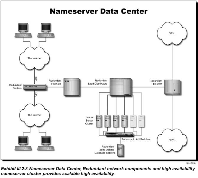
As discussed above, two nameserver sites are co-located at our SRS Data Centers and the remaining two nameservers System sites in Phase I are geographically dispersed with dual homed Internet and VPN local access telecommunications links to provide resilience and disaster recovery. The two additional nameservers sites will be installed in Data Centers in Melbourne, Australia and London, England. In phase II we plan to install additional nameserver data centers in Japan, California and Germany; if required to handle DNS query load.� The functional block diagram of our nameserver sites is depicted in Exhibit III.2-3. As can be seen from the exhibit the nameserver sites are configured to be remotely managed and operated �lights out�. The hardware configuration is highly redundant and designed for no single point of failure.
The following function directory table lists the nameserver functions.� Descriptions of the systems providing these functions are provided in the next subsection.
|
NAMESERVER FUNCTION DIRECTORY |
|
|
System Function |
Functional Description |
|
Zone Update
Database |
The SRS Zone Distribution Database is propagated to the
Zone Update Database Servers at the nameserver sites located worldwide.� Information propagated includes domain
names, their associated nameserver names, and the IP addresses for those nameservers. |
|
Nameserver |
The nameserver
handles resolution of TLD domain names to their associated nameserver names
and to the IP addresses of those nameservers. The nameservers are dynamically
updated from the Zone Update Database.�
Updates are sent over the VPN Registry Management Network. |
|
Building LAN |
Provides dual redundant switched 1000BaseTX Ethernet LAN-based connectivity for all network devices in the data center |
|
Firewall |
Protects the building LAN from the insecure Internet via a Firewall that provides policy-based IP filtering and network-based intrusion detection services to protect the system from the Internet hacking and denial of service attacks. |
|
Load Balancers |
Dynamic Feedback
Protocol (DFP) � based load balancing of TCP/IP traffic in a server cluster
including common protocols such as least connections, weighted least connections,
round robin, and weighted round robin. |
|
Telecommunications� Access |
Dual-homed access links to Internet Service Providers (ISPs) and Virtual Private Network (VPN) services are used for connectivity to the Internet and the JVTeam Registry Management Network. |
III.2.1.1.3���� SRS Data Center and Nameserver Buildings
Each JVTeam data center facility is located in a modern, fire-resistant building that offers inherent structural protection from such natural and man-made disasters as hurricanes, earthquakes, and civil disorder.� Sites are not located within a 100-year flood plain.� Facilities are protected by a public fire department, and have their internal fire-detection systems connected directly to the fire department.
Data centers are protected from fire by the sprinkler
systems of the buildings that house them. Furthermore, each equipment room is
protected by a pre-action fire-suppression system that uses Inergen gas as an
extinguishing agent.
The environmental factors at the SRS Data Center and nameserver sites are listed in the following table.
|
Heating, ventilation, and air conditioning |
Dual redundant HVAC units control temperature and humidity.� Either unit will maintain the required environment. |
|
Lighting |
2x2-foot ceiling-mounted fluorescent fixtures |
|
Control of static |
All equipment-mounting racks are grounded to the building�s system, and are equipped with grounding straps that employees wear whenever they work on the equipment. |
|
Primary electrical power |
208-volt, 700-amp service distributed through four power panels |
|
Backup power supply |
� 30 minutes of 130-KVA UPS power � 1000-KVA generator (SRS data center) � 250-KVA� generator (nameserver data center) |
|
Grounding |
� All machines are powered by grounded electrical service � A 12-gage cable under the equipment-room floor connects all equipment racks to the building�s electrical-grounding network |
Building Security
In addition to providing physical security by protecting buildings with security guards, closed circuit TV surveillance video cameras, and intrusion detection systems, JVTeam vigilantly controls physical access to our facilities. Employees must present badges to gain entrance, and must wear their badges at all times while in the facility. Visitors must sign in to gain entrance. If the purpose of their visit is found to be valid, they are issued a temporary badge; otherwise, they are denied entrance. At all times while they are in the facility, visitors must display their badges and must be escorted by a JVTeam employee. Sign-in books are maintained for a period of one year.
Security Personnel
On-site security personnel are on duty 24 hours a day, 7
days a week to monitor the images from closed-circuit television cameras placed
strategically throughout the facilities. Security personnel are stationed at
each building-access point throughout normal working hours; at all other times
(6:30pm to 6:30am and all day on weekends and major holidays), individuals must
use the proper key cards to gain access to the buildings. Further, any room
housing sensitive data or equipment is equipped with a self-closing door that
can be opened only by individuals who activate a palm-print reader. Senior
facility managers establish the rights of employees to access individual rooms,
and ensure that each reader is programmed to pass only those authorized
individuals. The palm readers compile and maintain a record of those
individuals who enter controlled rooms.
III.2.1.2����� Shared Registration System Descriptions�
This section provides system descriptions of the JVTeam SRS Data Center site and the Nameserver Data Centers. We provide brief system descriptions and block diagrams of each functional system within the two sites and their network connectivity.� The JVTeam registry system architecture central features are as follows:
� Co-active redundant data centers geographically dispersed to provide mission critical serviceavailability due to two-way database replication between the centers.
� Nameserver sites are designed with full redundancy, automatic load distribution, and remote management for �lights out� operation.
� A Virtual Private Network to provide a reliable, secure management network and dual homed connectivity between the data centers and the nameserver sites.
� Each SRS data center and nameserver site uses high availability cluster technology for flexibility, scalability, and high reliability.
� Registry systems are sized initially to handle the projected workload but can grow incrementally to accommodate workload beyond the current registry operations.
� The registry database uses fault tolerant server architecture and is designed for fully redundant operations with synchronous replication between the primary and secondary.
�JVTeam is proposing moderate-level, mid-level, and high-end cluster server platforms for installation at each site. The servers are selected for applications depending on the requirements, storage capacity, throughput, interoperability, availability, and level of security. These server platform characteristics are summarized in the following table.
|
Platform |
Features |
Application |
|
Moderate-level Intel Server Clusters |
Rack-mounted
Intel 700 Mhz, 32-bit, 2 to 6-way SMP CPUs with 8 GB of ECC memory, CD ROM,
four hot-swap disk drives (9-36 MB each), redundant hot swappable power
supplies, dual attach 100 BaseT Ethernet Adapter, clustering and event management
software for remote management. Microsoft� Windows NT� 4.0, Windows� 2000; Red
Hat Linux 6.1, C-2 Controlled Access protection security |
� Nameserver Cluster � Whois Server Cluster � Backup Server � Network Management Server �
Update
Servers (Zone/Whois) |
|
Mid-level RISC
Server Clusters |
Rack-mounted RISC
550 Mhz 2 to 8-way SMP, 64-bit CPUs, 32 GB ECC RAM, 72 GB internal disk
capacity, 71 TB external RAID, redundant hot swappable power supplies, dual
attach 1000 BaseTX/FX Ethernet Adapter, clustering and event management
software for remote management. Unix 64-bit operating system with C-2 Controlled
Access protection security |
� XRP Server � Web Server � Application Server Cluster � Billing & Collection Server � Authentication Server � Whois Database Server |
|
High-End RISC
Server Cluster |
RISC 550 MHz CPU,
64-bit 2 to 32-way cross-bar SMP with 8x8 non-blocking multi-ported crossbar,
32 GB ECC RAM, 240 MB/sec channel bandwidth, 288 GB Internal mass storage, 50
TB external RAID storage, redundant hot swappable power supplies, dual attach
1000 BaseTX/FX Ethernet Adapter, clustering and event management software for
remote management. Unix 64-bit operating system with C-2 Controlled Access protection
security |
Fault Tolerant
Server for database system |
III.2.1.2.1���� SRS Data Center System Descriptions
As previously shown in Exhibit III.2-2 the SRS data centers provide co-active fully redundant system configurations with two-way replication over the high speed VPN Registry Management Network, a co-located complete nameserver, and dual-homed connectivity to the Internet Service Providers. Descriptions of each of the systems in the SRS Data Center site are as follows.
XRP Server Cluster
XRP transactions received from registrars over the Internet undergo front-end processing by the XRP Server which manages the XRP session level dialog, performs session level security processing, and strips out the transaction records. These XRP transaction records are sent to the SRS data center application server cluster for security authentication and business logic processing.� The XRP server is a mid-level RISC SMP machine with local disk storage.� It off-loads the front end processing of the XRP protocol and off-loads the extensive communication protocol processing, session management and SSL security encryption/decryption from the applications servers. The XRP server strips the fields out of the XML document transaction and builds XRP binary transaction packets that are sent to the application server for initial security authentication and log on with user id and password.� Once the user is authenticated, the session is active and the XRP application server performs all business logic processing, billing, collection, and database operations.
Nameserver
A complete nameserver for DNS queries is co-located in each SRS data center site.� As previously shown in Exhibit III.2-3 the nameserver consists of redundant Internet Service Provider (ISP) and Virtual Private Network (VPN) local access links to provide alternate routed connectivity to Internet users and JVTeam�s Registry Management Network. Redundant Internet Firewalls provide policy-based IP filtering to protect our internal building LAN from intruders and hackers.
Application Server Cluster
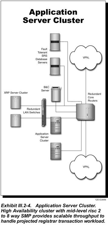
The application server cluster is a high availability multiple computer cluster. Each computer within the cluster is a mid-level processor with its own CPU, RAID disk drives, and dual LAN connections. Processor nodes used in the clusters are RISC symmetric multiprocessor (SMP) architectures scalable in configurations from 2 to 8-way with the processing and storage capacity for very large applications. As depicted in Exhibit III.2-4, the application server cluster is designed to handle the registrar transaction workload and provides the business logic processing applications and interfaces to the authentication server, SRS database, and billing and collection system. The application server cluster is front-ended with a TCP/IP load balancer to equitably distribute the processing load across the cluster processors. The cluster manager software monitors hardware and software components, detects failures, and responds by re-allocating resources to support applications processing. The process of detecting a failure and restoring the application service is completely automatic�no operator intervention is needed.
Fault Tolerant Database Server
The database server consists of two identical Fault-tolerant RISC systems that are designed for high volume on-line transaction-processing (OLTP) database applications. Each server contains high-end RISC processors scalable in configurations from 2 to 32-way. A crossbar-based symmetric multiprocessor (SMP) memory subsystem is capable of supporting the up to 32 GB of memory needed to maintain high OLTP transaction workloads. The storage subsystem supports up to 288 GB of internal RAID storage and up to 50 TB of external RAID storage. The database management software is based on a parallel database architecture with a fault tolerant server option capable of maintaining 24 x 7 availability. The Fault-Tolerant Server supports high availability operations by implementing synchronous replication. The database enables transparent database fail-over without any changes to application code or the operating system. Clients connecting to a replicated database are automatically and transparently connected to the replicated pair of databases. The database replication feature enables maintaining geographically separated data services for multiple sites over a WAN to provide disaster recovery.�
A multi-session, multi-threaded server and dual cache architecture (client/server) provides exceptionally high throughput and fast access to stored objects. A powerful database-driven publish and subscribe event notification system enables applications such as Whois or Zone Distribution to subscribe to a specific SRS database activity, for example, a domain name insert. When the domain name insert occurs, an event is generated by the database to be handled as a dynamic update to the Whois and Zone distribution servers.
Whois Distribution Database
Certain SRS database events such as a domain name insert, domain name delete, or domain name change, generate a notification to subscriber databases such as the Whois Distribution Database.� Modifications to the Whois Distribution Database are replicated to the Whois Database Clusters.
Whois Database
The Whois architecture gives the flexibility to deploy Whois database to any number of JVTeam Data Centers.� In the initial phase the Whois infrastructure will be deployed to the two SRS Data Centers.� However in the future, and based on load placed on the initial two Data Centers, additional infrastructure can be deployed to any of the nameserver Data Centers managed by JVTeam.
Each Whois Database receives replicated updates from the Whois Distribution Database.� The initial Whois Database will consist of two mid-level RISC database servers configured in a high availability cluster with RAID storage and from 2 to 8-way SMP processors. Since data is cached in the Whois Servers, the Whois Database is hit only when a Whois Server has not cached a request in memory.
Whois Server Cluster
The Whois service is available to anyone and can receive transaction volumes in the order of one billion requests per day. The cluster is a rack mount Intel Pentium-based high availability multiple computer cluster that maintains a separate database for domain name registrations and caches commonly requested records.� Processor nodes used in the Whois cluster are moderate-level Intel Pentium SMP machines scalable in configurations from 2 to 6-way SMP with local disk storage.
The Whois database contains information about Registrars, Domain names, nameservers, IP Addresses and the contacts associated with them. �This is an improvement over the current registry that provides no end-user contact information.� The Whois server cluster is front-ended with a load balancer designed to distribute the load equitably to the servers in the cluster and handle extremely high volumes of queries. The load balancer tracks processor availability and maintains high query processing throughput.
Zone Distribution Database
The Zone Distribution Database is dynamically updated from the SRS database using the same technique used for the Whois Distribution Database.� The Zone Distribution Database is propagated to Zone Update Database at the nameserver sites using replication. This approach is far better than the current approach of TLD Zone File updates for .com, .net, and .org that occur two times per day.
Billing and Collection Server
The Billing and Collection server is a LAN-based mid-level RISC machine in configurations scalable from 2 to 8-way SMP with the processing and storage capacity for very large enterprise applications. This server runs a commercial off the shelf customer relationship management and billing and collection system that interfaces with the SRS database.
Secure Web Server Cluster
A high capacity secure Web Server cluster is provided to enable secure web services and information dissemination that is outside the scope of the XRP protocol.� It contains a registry home page to enable registrars to sign in and inquire about account status, get downloads and whitepapers, access frequently asked questions, obtain self help support, or submit a trouble ticket to the TLD Registry Help Desk. The Web Server is a mid-level RISC SMP machine with local disk storage.
Authentication Server
The authentication server is a LAN-based mid-level RISC machine scalable in configurations from 2 to 8-way SMP with local RAID storage. This server runs commercial x.509 certificate based authentication services and is used to authenticate the identity of Registrars and optionally Registrants.� In addition, the authentication server supports our secure Web Server portal for Registrar Customer Service functions.
Backup Server
The backup server is an Intel Pentium-based SMP server that runs the backup and restore software to backup or restore each of the various cluster servers and database servers and provide a shared robotic tape library facility. It interfaces to the Intel server clusters and RISC server clusters over a high speed Fiber Channel bridge. It interfaces with the high-end fault tolerant database servers via a Disk Array and the Fiber Channel bridge to that interconnects to the robotic tape library. It is capable of performing remote system backup/restore of the nameservers over the VPN-based Registry Management Network.
System/Network Management Console
The system/network management console provides simple network management protocol (SNMP) monitoring of the network, LAN-based servers, cluster servers, and key enterprise applications including the XRP, Web, Whois, Zone, Billing and Collections, and database application. The server is a LAN-based moderate-level Intel Pentium-based SMP machine with local RAID disk storage and dual attach LAN interconnections.
Building LAN Backbone
The redundant switched Gigabit Ethernet building LAN backbone gives unprecedented network availability via redundant Gigabit Ethernet switches. Devices are dual attached to each of the Gigabit switch to provide a redundant LAN architecture. The building LAN is protected from the insecure Internet via a Firewall that provides IP filtering and network-based intrusion detection services to protect the system from the insecure Internet hacking and denial of service attacks.
Dual-Homed Telecommunications Access
We are using dual-homed high-speed Internet local access telecommunications links to two separate ISP providers These links will be alternately routed to provide resilience against cable faults and loss of local access telecommunications links. Similarly the telecommunications access links to our VPN provider for the Registry management network will be dual homed and alternate routed.
III.2.1.2.2���� Nameserver Description
Two nameserver sites are co-located at our SRS Data Centers and the remaining nameservers are geographically dispersed with dual homed Internet and VPN local access telecommunications links to provide resilience and disaster recovery.� The additional zone server clusters will be installed in Data Centers in Melbourne, Australia and London, England. The functional block diagram of our nameserver is previously depicted in Exhibit III.2-3.� As can be seen from the exhibit the nameserver sites are configured to operate �lights out�.� The hardware configuration is highly redundant and designed for no single point of failure and exceptionally high through put.� The following are the nameserver subsystem functions:
Zone Update Database
The Zone Distribution Database at the SRS Data Center is propagated to the Zone Update Database using replication.� Replication takes place over the VPN Registry Management Network.� The Zone Update Database is not hit when resolving DNS queries; instead the nameservers update their in-memory database from the Zone Update Database, within defined service levels.
Nameserver Cluster
The nameserver cluster handles resolution of TLD domain names to their associated nameserver names and to the IP addresses of those nameservers.� The resolution service can handle in excess of 1 billion queries per day, and our load-balanced architecture allows additional servers to be added to any nameserver cluster to allow on-demand scalability.
The nameserver Cluster is a high availability rack-mounted multiple computer cluster consisting of moderate-level Intel Pentium-based SMP machines configurable from 2 to 6-way SMP with local disk storage and dual attachment to the LAN. A TCP/IP server load balancer switch is used to distribute the load from Internet users. The server load balancer uses dynamic feedback protocol to enable servers to provide intelligent feedback to the load balancer to ensure that traffic is not routed to over-utilized servers. The load balancer supports algorithms including least connections, weighted least connections, round robin, and weighted round robin.
Building LAN Backbone
A redundant switched Ethernet building LAN backbone maintains high network availability via redundant Ethernet switches. Devices are dual attached to each of the Ethernet switches to provide a redundant LAN architecture. The building LAN is protected from the insecure Internet via a Firewall that provides IP filtering and network-based intrusion detection services to protect the system from the insecure Internet hacking and denial of service attacks.
A summary of the features and benefits of our TLD registry system architecture are provided in the following table.
|
Feature |
Benefit |
|
Three classes of scalable processor configuration � moderate-level, mid-level, and high-end |
Provides flexible
processing power and scalability to the applications |
|
Direct Access
Storage up to 50 Terabytes for database applications |
Unmatched storage
scalability of the database |
|
Switched Gigabit
Ethernet Redundant building LAN architecture |
High capacity LAN
infrastructure with no bottlenecks |
|
Full Redundancy
of all critical components with no single point of failure |
Zero downtime and
zero impact to users |
|
Dual-homed,
alternate routed local access links to two separate Internet Service
Providers |
Maintains
connectivity if one of the ISP�s services should experience and outage |
|
Dual-homed, VPN
connections to the VPN service provider |
Protects against
digging accidents that could damage local access cables |
|
Fault Tolerant parallel database architecture configured for high OLTP transaction throughput |
Non-stop database
services and throughput scaled� to
handle all registry operations out of one data center. |
|
Load balancing
session distribution algorithm (SDA) to intelligently and transparently
distribute traffic across servers |
Maximize the
number of Transmission Control Protocol/Internet Protocol (TCP/IP)
connections managed by a server farm. |
|
Separate Whois
Server cluster and datamart to process Whois transactions |
Facilitates rapid
response to Whois queries. |
III.2.1.3����� Registry Network System Description
JVTeam is using the Internet to provide connectivity to the Registrars and a Virtual Private Network (VPN) to provide a secure Registry Management Network for communications between the SRS data centers and the nameserver sites.
III.2.1.3.1���� Internet Connectivity
JVTeam estimates the peak Internet bandwidth demand at the SRS data centers to be between 5 and 10MB. We will deploy two 45MB T-3 local access telecommunications links at each of our data centers, enabling each to provide TLD services independently of the other.� We will provision 5MBs of capacity on each of the T-3 links.� Therefore we will provision 10MB into each nameserver site and have up to 90MB (2 x 45MB) of capacity for growth.� This should be sufficient growth for at least two years.�
Connectivity to each data center will be via redundant routers.� For security purposes, the router will be configured to only allow DNS UDP/TCP and BGP4 packets.� Each router is connected to a load balancer that distributes the query load among the nameservers in that site�s cluster. These links will be alternately routed to provide resilience against cable faults and loss of local access telecommunications links. Similarly the telecommunications access links to our VPN provider for the Registry Management Network will be dual homed and alternate routed. Redundant routers are used for both Internet and VPN access.
III.2.1.3.2���� VPN Registry Management Network
Each SRS Data Ceneter is connected to each of the nameserver sites over a VPN.� In addition there are two ATM links that connect the two SRS Data Centers.� Like the internet access the ATM links will be delivered over a T-3 local access link.� Each link will be configured with some fraction of the full 45 MB of bandwidth.� At the nameservers the two VPN connections will be delivered over a 1.5MB T-1 local access link.� The bandwidth on each of the VPN circuits will be some fraction of the full 1.5MB.� The VPN Registry Management Network is a secure network used for JVTeam internal registry information exchange. It handles:
� Nameserver database replication from the Zone Distribution Database to the Zone Update Database at the nameserver sites.
� Remote System/Network Management/Backup of the nameservers.
� Remote Administration of nameservers.
III.2.1.4����� Registry System Application Software
Planning for the potential growth associated with domain registration and administration requires vision and a flexible design.� JVTeam�s vision is to successfully conduct leading edge software engineering and product development.� JVTeam�s proven record of successful development and implementation of large projects benefits ICANN by reducing technical and schedule risk.
JVTeam software components are developed using open system and software standards to facilitate cost effective application expansion and upgrade.� The Registry functional design consists of a number of components representing a blend of:
� Proven, software design and development methodology
� Change management and deployment process
� Proven, mission-critical-grade, third-party software products to complement the JVTeam-built software components.
III.2.1.4.1���� Registry Application Components
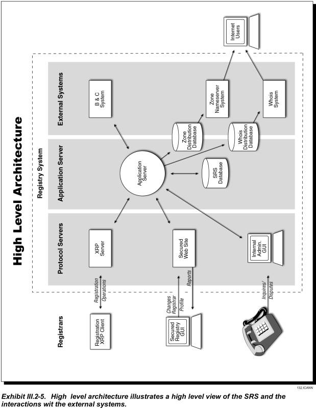
The following components, illustrated in Exhibit III.2-5, deliver the Registry application functionality:
� Protocol Adapters
� Web Server (Presentation) Component
� Application Server Component
- Process Manager
- Processing Engines
� Whois Component
� Nameserver Component
� Billing and Collections Component
� Datastore
Further information regarding these components is presented in the following
sections.
Protocol Adapter Component
The protocol adapter component is the software module running on the XRP protocol servers.� This component provides the standards based interface between the Registry and Registrar systems.� The XRP protocol will be based on open industry standards such as:
� XML�JVTeam proposes the introduction of a new standard protocol, the eXtensible Registry Protocol (XRP), based on XML.� This protocol supports system level communication between the Registrar and the Registry.
� SSL�X.509 Certificates will be used over an encrypted SSL session to authenticate Registrars (in addition to IP based and user id/password security).
The protocol adapters will receive secure, encrypted data from Registrar systems.� They will convert the verbose external XML message into a compact binary internal message format, which is delivered to the application server�s process manager for processing.� When processing is complete, the process manager will send the binary internal message back to the protocol adapters for conversion to the protocol appropriate for communicating with the external system (i.e. XRP)
The protocol adaptor architecture allows JVTeam to support a simple but powerful XML based protocol supporting a comprehensive security policy, while eliminating additional load that would otherwise be placed on the core SRS system.
Application Server Component
The design of the application server component is modular and flexible to support the requirements and scale to meet demands placed on the system.� The application server utilizes a stateless architecture allowing scalability simply by adding additional machines to the tier.� The core business logic is built into the application server component.� This component manages all back-end resources and performs services such as connection pooling and monitoring.�
The process engines defined in this section are some of the major functional components of the system.� Process engines will be added and configured to meet the functional requirements.
Process Manager�is used to manage the different processes supported by the application. This includes starting processes in a specific order at initialization time, monitoring the health of executing processes, restarting failed processes and starting new processes to address application load requirements.� The process manager mediates processing and information requests from external systems by forwarding requests to the respective process engines.
Process Engines�will perform the underlying processing steps or primitives that are involved in performing the operation. The Process Engines receive data and parameters from other application components, including Process Manager. The Process Engines access data from databases, and update the databases while processing a transaction. The primary process engines are:
� Domain Name Administration
� Registrar Administration
� Whois Administration
� Zone Administration
� Security
� Billing and Grace period Administration
� Logging, Auditing & Reporting
The functionality of the primary process engines are explained in detail in sections III.2.3 and III.2.6.
Datastore
The SRS architecture includes a fault-tolerant database supporting high availability operations by implementing synchronous replication. This enables transparent database fail-over without any changes to application code or the operating system. Clients connecting to a replicated database are automatically and transparently connected to the replicated pair of databases.
The architecture utilizes a powerful database-driven publish and subscribe event notification system enabling components such as Whois or Zone Distribution to subscribe to specific SRS events.� Subscribed events cause dynamic updates to the Whois and Zone distribution servers.
Please refer to section III.2.3 for a detailed description of the Database capabilities.
Registry Web Interface
The guiding principles for the design of the proposed Registry Web Interface are flexibility and security.� The Registry web interface will be accessible over the Internet, using a client web browser and will be served up by the Registry web server clusters at the SRS Data Centers.� The secure web servers provide front-end HTTPS (secure web) protocol handling with client browsers accessible over the Internet.
Some of the key features of the Registry Web Interface Architecture include:
� Extensible Design
� Open, non-proprietary, standards-based technology (HTTP + SSL).
� Intuitive user interface
� Secure access
� On-line help
� Ease of navigation
� Data entry type checking (before forwarding requests to the application server tier)
Billing and Collection System
JVTeam will combine our customized B&C methodology that has proven successful in the past with an off-the shelf, accounts receivable product to provide comprehensive, secured, high quality, scalable, and web accessible B&C service. The major components of the system will include
� Database
� Transaction Processor
� Monitor & Notifier
� Report Generator
Please refer to section III.2.6 for a detailed description of the Billing and Collection system along with the interfaces, security and access privileges.
Nameserver Component
Zone related modifications to the SRS Database cause equivalent changes to the subscribing Zone Distribution Database.� Updates to the Zone Distribution Database are replicated out to the Zone Update Databases at each nameserver Data Center.� Machines in the nameserver Cluster reconcile their in-memory database with the Zone Update Database at regular intervals defined in the service level agreement.� The entire Zone is held memory resident.
Section III.2.5 explains nameserver architecture is detail, along with the process, software and advantages.
Whois Component
Whois related modifications to the SRS Database cause equivalent changes to the subscribing Whois Distribution Database.� Updates to the Distribution Database are replicated to the Whois Database Cluster at each SRS Data Center.� Machines in the Whois Server Cluster cache common requests in-memory, taking load off the Whois Database Cluster.� Cached items expire after a defined time interval to ensure Whois data can be guaranteed correct within defined service levels.�
Please refer to section III.2.8 for a detailed description of the Whois capabilities.�
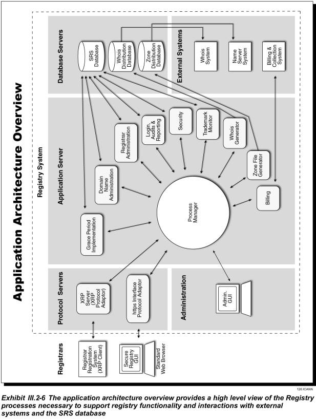
Exhibit III.2-6 provides a more detailed application architecture overview.
III.2.1.4.2���� Registry Software Development Methodology
The quick time to market and software technologies required to design and implement the registry software applications dictate software development methodologies that minimize software development and reduce development time without sacrificing software quality. The JVTeam technical personnel are experts in software applications development of registry and clearing house protocols and software applications used in Internet domain names and phone numbering systems. The benefit to ICANN is software products that meet the functional requirements and operate reliably.
Based on our experience, JVTeam is using Rapid Application Development (RAD) methodology and Computer Aided Software Engineering (CASE) tools for registry software applications development. RAD methodology enables large applications systems to be developed and tested incrementally in planned releases consisting of alpha, beta, and full production versions. We have found that incremental development of software applications is a key success factor in fielding feature rich software applications that meet the business needs. This is because each incremental build provides a testable software product that can be demonstrated to users and stakeholders. Changes can be easily incorporated in the next build cycle and each successive build provides increased functionality until the full production release is completed, tested, and accepted.
RAD Methodology
In the RAD methodology there are five phases.
1. Business Analysis�Focus group and Joint Application Design sessions are used to document the system requirements, business process flows. business logic, and system data requirements.
2. System Design�Software specifications are developed using object oriented analysis and object oriented design CASE tools and logical data models are developed using entity relationship diagram data modeling. Meta data is developed for each data entity.
3. Architecture Design�the system hardware and software architecture is designed and documented. Then hardware and software systems specifications and configurations are developed and finalized for acquisition.
4. Implementation�the applications software is developed for the target hardware platforms and operating system environment using object oriented programming languages, database development tools, and fourth generation languages. Development test beds are built for software testing. The applications software is built and tested in increments with the functionality growing with each build from alpha to beta and to full production. The system hardware and software is installed in the planned data centers for rollout and acceptance of the applications software production release. The Carnegie Mellon University Software Engineering Institute Software Capability Maturity Model (SW-CMM) best practices are used for project management, requirements management, software configuration control, and software quality assurance.
5. Growth and Maintenance�during this phase the applications software is successively upgraded in planned build and release cycles. Software incident reports are addressed in each build and release. Maintenance releases are developed for serious software problems that cannot wait until a planned upgrade release.
Development Tools and Languages
JVTeam is using object-oriented analysis and object-oriented design CASE tools for requirements analysis and detailed software design. We use object oriented programming, database development tools, and fourth generation programming languages for software development. The following table gives examples of tools JVTeam has used in the past and will use on the Registry project.
|
Development Tool/Language |
Purpose |
|
CASE Tools |
JVTeam will utilize CASE tools such as Oracle CASE and Rational Rose.� These tools provide full feature object oriented analysis and design. |
|
Java, C++, Delphi, SQL |
JVTeam has prior experience with, and will utilize these development languages where appropriate to implement all business logic. |
|
CORBA, RMI |
JVTeam has prior experience with, and will utilize these Remote object protocols. |
|
Java Servlets,
Java Server Pages, Cold Fusion, CGI-script, XML & XSL |
JVTeam has prior experience with, and will utilize these web development technologies for building web sites and thin client applications for distribution to a wide range of users. |
III.2.2�������� Registry-Registrar Model and Protocol (RFP Section D15.2.2)
This section describes existing numerous problems with the current Registry-Registrar model and RRP protocol, and provides JVTeam�s proposed methods for resolving these problems.
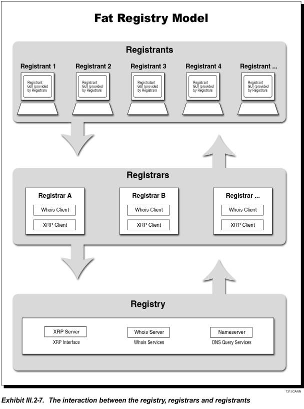
The current registry/registrar model and protocol is a �thin� (limited amount of data) registry serving a fat (more data) registrar.� JVTeam proposes moving to a �fat registry� model, with contact and authentication details stored centrally at the Registry.� Under this model, the business relationships would be unchanged: registrants would still deal with the registrar, and the registrars with the registry.� The value of the proposed change is its ability to solve many of the problems currently experienced on a daily basis by both Registrants and Registrars.
As part of its fat-registry proposal, JVTeam proposes to introduce a new protocol, the eXtensible Registry Protocol (XRP), which will overcome the limitations of the current RRP protocol (RFC2832).� The XRP protocol will accommodate both thin and fat registry models.� We do not anticipate introducing the XRP protocol until after the �land rush� period has ended.
III.2.2.1����� Problems With The Current Model and its Supporting Protocol (RRP)
The current TLD is based on a thin registry model and the RRP protocol.� Problems with the system cause confusion for registrants and have added costs (and risk) to registrars because of the need for manual processing or the breakdown of automated processes.� The following table lists issues with the current model and RRP and gives example relating to these issues:
|
Deficiencies of the current registry/registrar model and protocol |
|
|
Issue |
Result |
|
Protocol not extensible |
� No ability to authenticate registrants � Not designed for fat registry model � Not designed using a naturally extensible technology, such as XML |
|
Protocol not complete |
� Not all data exposed (e.g., registrar details and status not exposed) � No ability to query transfer status � No date/time of registration and expiration � No status on domains linked to another registrar |
|
Different protocols used for Whois |
� No uniform Whois standard (registrars can use web interface) � Not all registrars use Whois on Port 43 |
|
No standard Whois fields |
� Each registrar has implemented Whois differently.� Differences include: � Some registrars have additional registrant contact information � No standards exist for technical and/or zone contact � Some registrars have one address line; others, two lines � Some registrars don�t expose all fields in the Whois |
|
Different data formatting in Whois services |
� Data is presented differently; i.e., Phone: 99999 or Phone Number: (999) 999 � Different ordering of fields � Different lengths of fields |
|
No real-time update of Whois and zone file |
� Registry updates Whois and root servers only every 12 hours � Causes confusion for Registrants, adds support cost to Registrars |
|
Timing inconsistencies (when adding, deleting, transferring registrar, etc) |
� Registry Whois server updated before or after Registrar database, causing inconsistency between the two � Two registrars� databases can be updated at different times, causing inconsistency |
|
No machine-readable Whois format |
� No automated parsing of Whois data by non-registrar community (Need XML-based Whois format) |
|
No registrar extensibility |
� No provisions for registrars to add custom fields to registry database except after revising the protocol |
|
No ability to broadcast events to registrars |
� Registry cannot automatically notify Registrars of important events (e.g., �Transfer of Registrar� request or renaming of a name server host name); must use email � Cannot accommodate registrars� need to add �listeners� to certain important events |
|
No registrant authentication |
� Cannot determine whether a registrant�s �Transfer of Registrar� request is authentic.� The registrar must make a subjective decision about whether the registrant is the one represented in the losing Registrar�s Whois � No standard method for authenticating deletions, changes of ownership, re-delegations, name-server maintenance, etc � TLD security sinks lowest common (registrar) denominator, because a registrar with poor security could perform an incorrect Transfer of Registrar, giving the registrant control of the wrong domain name.� Potential for �hijacked� domain names creates huge stability problems to the Internet. |
|
No rollback support for some operations |
� Not all operations can be reversed by a separate counteraction (although some can: e.g.,� �Register domain name� can be reversed by �Cancel domain name� command within 5 days) � Operations like Registrar Transfer cannot be �rolled-back� via the protocol in the case of error |
|
No support for IPv6 |
� Does not support important, currently deployed technology |
III.2.2.2 ���� Features of the Fat Registry Model
As the beginning of this proposal paragraph (III.2.2) states, JVTeam proposes deploying a �fat registry� model, with contact and authentication details stored centrally at the Registry.� Exhibit III.2-7 illustrates the fat registry model.��
JVTeam prepared the following list of design features for our proposed
XRP protocol:
� Extensible protocol based on XML
� Support for both fat and thin registry models
� Support for centralized contact information / centralized Whois
� Standardized Whois service (same fields regardless of registrar�s web site)
� Machine readable Whois format (when specified)
� Extensible data-field support (registrars can add custom fields to Whois following standardized fields)
� Functionally complete (exposing all registry data via one interface)
� Secure
� Non-repudiation (No deniability)
� Fault tolerant (Duplicate requests have no adverse effect)
� Real-time XRP functions (check, register, etc)
� Real-time DNS and Whois updates
� Support for IPv6 IP addresses
� Standard, centralized registrant-authentication method
� Extensible registrant-authentication methods (support for digital certificates, etc)
� Simple account transfer (between registrars, using centralized authentication)
� Event broadcasting (ability for registrars to place �listeners� on registry events)
� Rollback support (i.e., rollback registrar transfer; not necessarily transactional).
JVTeam firmly believes that the industry needs a new extensible protocol that addresses all of the above points, and that the selected protocol should become the industry standard.� JVTeam�s position is that there is infinite room to innovate in many other aspects of domain-registry systems, but competition at the protocol level merely fragments the domain-name-registration industry.� Conversely, the industry will gain significantly in efficiency if it adopts a standard protocol that addresses the listed requirements, particularly in supporting both fat and thin Registry models.�
JVTeam�s proposed XRP protocol addresses each of the above points.� We will present a draft XRP to the IETF as the basis for an industry standard in Q4 2000, and will invite comments and suggestions from registrars, registries, and other concerned individuals and organizations.� Rather than holding XRP as proprietary, we will undertake all reasonable measures to obtain consensus on making the proposed protocol an open industry standard.
III.2.2.3����� Benefits of Proposed XRP Solution
JVTeam�s proposed XRP Solution and fat-registry model will preserve the current relationships that are familiar to both registrants and registrars.� Simultaneously, they will solve the many problems with the current RRP-based model that is raising costs for registrars and distressing registrants.�� Nonetheless, despite the fat-registry model�s obvious advantages, we are willing to consider alternatives.�
On the one hand it is theoretically possible retain the current thin-registry model and place more stringent technical requirements on registrars (while closely policing compliance). On the other hand, JVTeam believes that a more practical solution�the only solution that introduces true stability and domain security into the market�is moving to a fat-registry model with a new XML-based protocol that supports the many enhancements previously listed.� The XRP protocol�indeed, any new protocol�must be designed to fix all the problems with the current model and protocol.
To facilitate the transit in 2001 for current registrars, JVTeam will provide an open-source version of the registrar toolkit.� This enhanced toolkit will simplify the migration efforts of registrars that currently use the RRP toolkit only.
JVTeam is well qualified to take a lead position in the process of developing and standardizing the specification for a new protocol.� In preparing our proposal for building a modern, extensible protocol, we relied heavily on the extensive prior experience that Melbourne IT brought to JVTeam.� Research groups at Melbourne IT have been using XML for more than two years, and have developed two XML-based domain-name-registration interfaces.� Further, the company currently has XML-based interfaces in production.�
III.2.3�������� Database Capabilities (RFP Section� D15.2.3)
JVTeam will provide an enterprise-strength, fault-tolerant database system capable of managing large databases and high transaction-processing loads reliably, with scalable growth to accommodate change. The database system supports asynchronous replication of data between two co-active SRS data centers geographically dispersed.� The benefit to the Internet community is reliable, stable operations and scalable transaction-processing throughput to accommodate Internet growth.�
The heart of the SRS is its database systems, which provide not only simple data storage-and-retrieval capabilities, but also the following capabilities:
� Persistence�storage and random retrieval of data
� Concurrency�ability to support multiple users simultaneously
� Distribution (data replication)�maintenance of relationships across multiple databases
� Integrity�methods to ensure data is not lost or corrupted (e.g., automatic two-phase commit, physical and logical log files, roll-forward recovery)
� Availability�support for 24 x 7 x 365 operations (requires redundancy, fault tolerance, on-line maintenance, etc.)
� Scalability�unimpaired performance as the number of users, workload volume, or database size increases.
As applications architectures such as SRS become increasingly dependent on distributed client/server communications and processing, system designers must carefully plan where the bulk of the data processing occurs: on the database server, applications server, or client.� Our final design will distribute the processing workload in a way that maximizes scalability and minimizes down time.
This proposal paragraph (III.2.3) is divided into three major subsections:
III.2.3.1� Functional Overview�describes the characteristics of the three primary SRS databases (i.e., size, throughput, and scalability); database procedures and functions for object creation, editing, and deleting; change notifications; transfer procedures; grace-period functions; and reporting.
III.2.3.2� Database System Description�describes the database-system components, server platforms, and scalability for the three primary databases.
III.2.3.3� Security and Access Privileges�describe the access controls for granting and denying users and administrators access to the databases.
III.2.3.1����� Functional Overview
As shown in Exhibit III.2-8 in Proposal Paragraph III.2.1, JVTeam�s registry will include three major databases:
� SRS Database�This database�s primary function is to provide highly reliable persistent storage for all of the registry information required to provide domain-registration services.� The SRS database is highly secured, with access limited to authenticated registrars, trusted application-server processes, and the registry�s database administrators.�
� Billing and Collection Database�This database will provide the information required for JVTeam to render billing and collection (B&C) services to the registrars. Access to its data is limited to the trusted B&C system processes and to registry database administrators. Registrars can view billing data through a secure Web portal with a B&C Applications Programmer Interface (API).
� Whois Database�The Whois database is a searchable database that any Internet user can access to view details of the domain name stored in the SRS. The Whois database maintains data about registrars, domain names, nameservers, IP addresses, and the associated TLD contacts. The Whois database is updated from the SRS database through an intermediate database and replication process.
In addition to these databases, the registry will maintain various internal databases to support various operations, e.g., authorizing login userids and passwords, authenticating digital certificates, and maintaining access-control lists.
In implementing the SRS database systems, our system designers will carefully analyze the differing requirements for the three major databases and select the optimum solution for each.� Design techniques and considerations will include:
� Multiple logical data models that we will optimize for the different types of information that each system needs to serve registrars efficiently
� Content that will include data related not only to domain names and domain name registration, but also to registrars, registrants, nameservers, Whois servers, and the Billing and Collection system
� Differing volumes of database transactions and database sizes
� Differing business needs
� Differing performance and availability requirements
� Replication of databases to achieve high availability and facilitate backup/recovery.�

Database Size, Throughput, and
Scalability
The following table lists design parameters for the initial design of the three major databases.� The parameters are based on projected volumes in the first two (2) years.� Scalability term in the table refers to the database�s ultimate capacity expressed as a multiple of the initial design capacity in terms of size and transaction processing power.�
DATABASE DESIGN PARAMETERS |
||
SRS Database |
Design Parameter |
|
|
Domain registrations |
20 million |
|
|
Registrars |
100 |
|
|
Size of registration object |
10 K |
|
|
Total data |
190 G |
|
|
Database Management System (DBMS) and logs |
3 G |
|
|
Database indexing |
400 G |
|
|
Total size |
590 G |
|
|
Database throughput |
TpsC = 1050 |
|
|
Database scalability |
100 times in size 8 times in processing power |
|
|
Billing Database |
Design Parameter |
|
|
Billable events per month |
1 million |
|
|
Transaction size |
1 K |
|
|
Transactions per month |
1 G |
|
|
Historical data for 3 months |
3 G |
|
|
Registrars |
100 |
|
|
Registrar billing profile |
30 K |
|
|
Total billing-data |
3 M |
|
|
Total data |
3 G |
|
|
DBMS & logs |
3 G |
|
|
Database indexing |
6 G |
|
|
Total size |
12 G |
|
|
Database throughput |
TpsC = 353 |
|
|
Database scalability |
From 2-way to 8-way |
|
|
Whois Database |
Design Parameter |
|
|
Domain registrations |
20 million |
|
|
Registrars |
100 |
|
|
Size of registration object |
4 K |
|
|
Total data |
80 G |
|
|
DBMS & logs |
2 G |
|
|
Database indexing |
200 G |
|
|
Total size |
280 G |
|
|
Database throughput |
TpsC = 353 |
|
|
Database scalability |
2-way to 8-way |
|
Database Procedures and Functions
The database system is critical to the processing of SRS business transactions.� The SRS database and B&C databases are accessed during many registrar/registry transactions. If a transaction is completed successfully, the system not only updates these two databases but also the Whois distribution and Zone distribution databases.� (The latter two are periodically replicated to the Whois and Zone update databases, respectively.) This subsection describes the main procedures, objects, and data flows for the following registry functions:
� Object Creation�Domain name and nameserver registration
� Object Editing�Modifying domain name or nameserver data and creating or modifying associations
� Object Deletion�Domain name cancellations
� Object Existence and Information Query�Obtain information on domain name, nameserver, or contact name
� Object Transfer�Transfer a domain name to a different registrar
� Automatic Domain Renewal�Extend a domain name registration for a year
� Grace Period Implementation�Allow various time periods before actions become final
� Registrar Administration�Add, delete, or change to a registrar account or billing profile
� Billing Notifications�Account-related information sent to registrars and designated registry staff
� Reporting�Account and billing information that can be viewed on line or emailed
� Mass Updates�Special procedures; e.g., changing a registrar�s name on each of its domain name files if it is acquired by another registrar
� Trademark Monitor�A trademark registration, search, and notification capability.
The following paragraphs provide additional information about each of these functions.
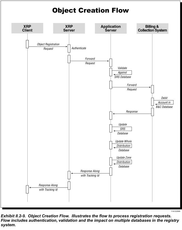
Object Creation (Register a Domain Name or Name Server)
Exhibit III.2-9 shows how a registrar registers either a new domain name or a nameserver.
� The registrar�s request arrives at the application server via the XRP server.
� The application server queries the SRS database to determine whether the domain name or nameserver is available.� If it is not, the application server notifies the registrar.
� If valid, the application server queries the Billing database to determine whether sufficient funds are available in the registrars account.� If not, the application server notifies the registrar.
� If funds are adequate, the registrar�s account is debited for the appropriate amount and the master database is updated to reflect the registration.
The process for registering a nameserver eliminates the billing steps.� The application server queries the SRS database to determine whether the nameserver name is available.� If it is, the application server updates the server with the new information; if it is not, the application server returns the error code to the registrar.
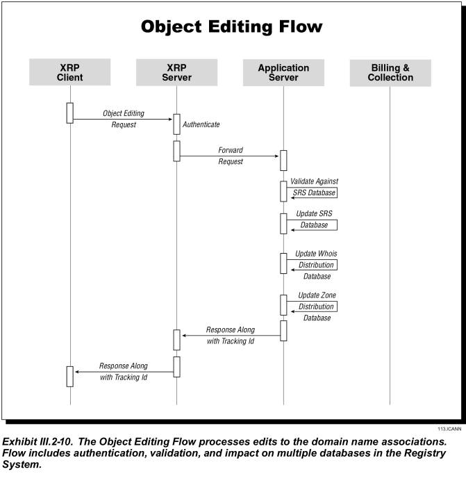
Object Editing
Exhibit III.2-10� shows how a registrar modifies and creates associations for an existing domain name.
� The registrar�s request arrives at the application server via the XRP server
� The application server queries the SRS database to validate the domain name and nameserver status
� If valid, the application server updates the SRS database; if not, it returns the error code to the registrar.
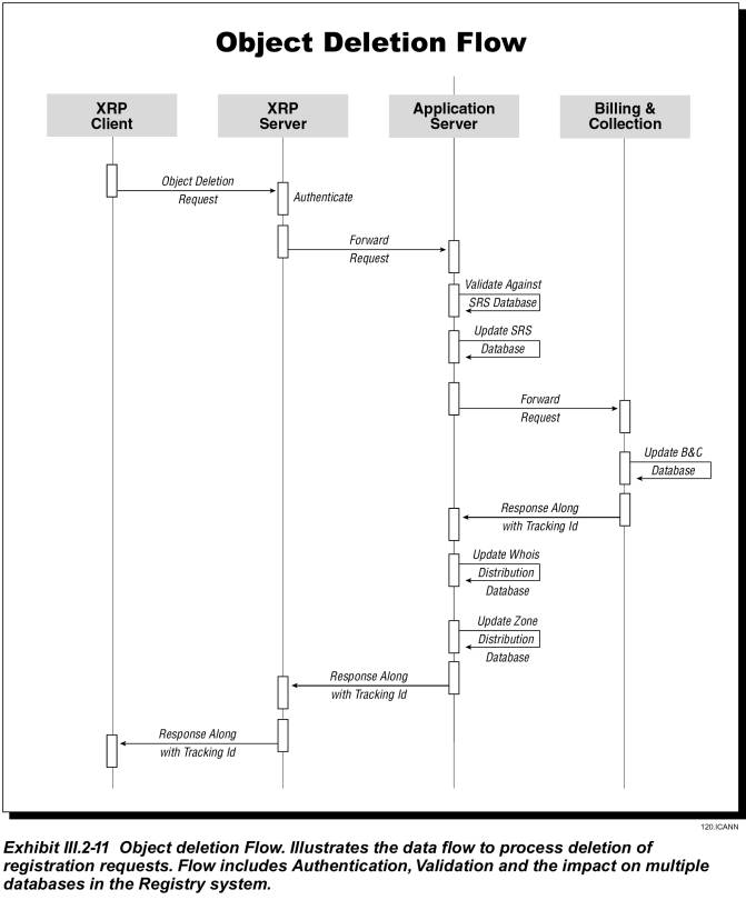
Object Deletion
Exhibit III.2-11 shows how a registrar cancels a domain name or a nameserver registration.
� The registrar�s request arrives at the application server via the XRP server
� The application server queries the SRS database to validate the status of the domain name, its associations or to determine that no domain names are associated with the nameserver to be cancelled
� If valid, the application server updates the SRS and Billing databases; if not, it returns the error code to the registrar.
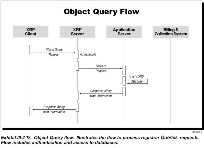
Object Existence &
Information Query
Exhibit III.2-12 shows how the system handles a query about a domain name, nameserver, or contact identifier.
� For an �Object Existence� query, the application server searches the SRS database and returns a positive or negative response
� For an �Object Information� query, the application server returns all information available for the requested object.
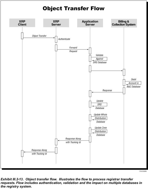
Registrar Transfer (of Domain Name)
Exhibit III.2-13 shows how a registrar can transfer a domain name registration from another registrar to himself.
� The registrar�s request arrives at the application server via the XRP server.
� The application server queries the SRS database to validate the domain name status.
� If valid, the application server notifies the losing registrar of the request and initiates the grace period to wait for losing registrar�s response.
� If the losing registrar does not respond within the grace period, or returns a positive acknowledgement, the application server queries the Billing database to determine whether the new registrar�s account has sufficient funds for the transaction.� If not, the applications server sends the new registrar an error code.
� If funds are adequate, the registrar�s account is debited for the appropriate amount and the master database is updated to reflect the new registrar.
Domain Renewal (Automatic)
If a domain name registration expires, the SRS automatically renews the domain name for one year. The application server performs this function as follows:
� It queries the SRS database to validate the status of the domain name.� If no longer valid, process terminates.
� If valid, the application server queries the Billing database to verify that the registrar�s account contains sufficient funds.� If not, it returns an error message to the registrar.
� If sufficient funds, registrar�s account is charged for one-year renewal and status is updated in SRS database.
Domain Renewal (Registrar-requested)
� A registrar�s request to renew a domain name arrives at the application server via the XRP server.
� The application server queries the SRS database to validate the domain name status.� If not, it returns an error message to the registrar.
� If valid, the application server queries the Billing database to verify that the registrar�s account contains sufficient funds.� If not, it returns an error message to the registrar.
� If sufficient funds, registrar�s account is charged for term of renewal and status is updated in SRS database.
Grace Period Implementation
JVTeam�s SRS will support grace periods for several registry functions.� The SRS database will manage the configurable data for implementing grace periods for such as the following grace periods:
� Automatic one-year renewal or extension of a domain name registration after it expires
� Grace period during which a registrar can cancel an automatic renewal
� Grace period during which a domain name remains unavailable after its registration has expired or been cancelled
� Grace period during which a registrar can cancel a domain name registration without any fee
� Grace period for waiting for losing registrar�s response before transferring a domain name registration to a new registrar.
Registrar Administration
Registrar administration refers to adding or deleting registrars, and to providing each registrar with secure access to the system and to that registrar�s data. The SRS database manages most registrar data; the Billing database contains the B&C profile and contacts.� Any �Add/Delete Registrar� or �Change Registrar Profile� request will generate the appropriate changes in the SRS and Billing databases.
Mass Updates
A typical mass update is a global change of a registrar�s name, which may occur when one registrar purchases another.� JVTeam will design procedures for mass database changes initiated by registrars or other authorized entities.�
Trademark Monitor
End users will be able to obtain trademark registration through registrars�and after agreeing to a �Terms of Use� policy�end users can access a trademark-search capability with the following characteristics:
� Trademark holders will be able to submit to their registrars a string of characters that they wish to protect as a trademark.
� Registrars will submit this string to the registry and request that it be monitored for trademark infringement.
� The registry will insert the string into a �Trademark monitoring� file in the SRS database.
� When the registry receives a �Request for domain-name registration� that includes the monitored string, it returns a notice that the string is a trademark, provides the contact information for the monitoring trademark holder, and informs the applying registrar of the grace period during which he may revoke the domain-name registration without penalty.� The registry then proceeds with registering the domain name.
� Registrars have the responsibility for alerting registrants if a domain name they have registered contains a sub-string being monitored by a trademark holder.
Billing Notifications
JVTeam�s Billing system will monitor the registrars� accounts for insufficient funds.� If it determines that the balance is below the required minimum, it notifies the registrar and the registry�s customer-service personnel.
Reporting Capabilities
To support a detailed, usage-based accounting and billing structure, the system generates a substantial amount of highly detailed resource-accounting data.� The following sources generate this data:
� Billing database
� Billing transaction-processing subsystem
� Batch-processing events (e.g., audits and reports)
� Internal-support records.
Monthly Account Statements�We will send a detailed monthly transaction statement to each registrar via email.� The statement will include the following:
� Account Summary, including payments received, balance forward, and credits and adjustments
� Detailed list of all fee-incurring charges; e.g., new registrations, registration renewals, registrar transfers.
Online Billing Reports�The system will generate a variety of reports for internal and external users.
� Using the Internet, registrars will be able to access their account statements and detailed transaction reports, but not those of other registrars.
� Registrars will be able to request custom reports. The system will generate these reports in a batch process, and will store them in the FTP directory for the requesting registrar to download.
Audit Reports�JVTeam will create audit reports for internal and external purposes. Audit reports will include:
� Policy implementation
� Permitted participants
� Capacity handling
� Accountability
� Revenue forecasts.
III.2.3.2����� Database System Description
Although the three primary SRS databases�SRS, Whois, and Billing�will differ, depending upon the services they support, the SRS on the whole, will be structured to:
� Manage large quantities of data
� Support applications that use data models with complex relationships
� Perform complex operations on these objects
� Process large volumes of transactions from users.
JVTeam forecasts that, as with most OLTP applications, the anticipated volume of SRS transactions will have a high ratio of �reads� to �writes.��� We will design the databases and applications by partitioning the workload to improve response times and scalability.
SRS Database
The SRS database will support and provide information for primary domain-registration services. The following table lists the data stored in the SRS database.
|
SRS DATABASE DATA |
|
|
Primary Element |
Details |
|
Domain Names |
� Domain Name Attributes (Status) � Associated Name Servers � Associated Registrar � Associated Registrant Data |
|
Nameserver |
� Nameserver Attributes (Status) � Associated IP Addresses � Associated Registrar � Associated Registrant Data |
|
IP Address |
� IP Address Attributes (Status) � Associated Nameservers � Associated Registrar � Associated Registrant Data |
|
Registrar List |
Registrar Names |
|
Registrars |
� Registrar Name � Registrar Contact Details � Registrar URL (Home page) � Registrar Whois URL (Web Port 80) � Registrar Whois URL (Port 43 � If Applicable) � Registrar Attributes (Status) |
|
Trademark Monitoring |
� Trademark � Monitoring Trademark Holder contact |
JVTeam will configure the database system to provide appropriate response times for the transactions that registrars perform. We will do capacity planning to ensure that as business requirements increase and demand for domain names grows, the system will be able to handle the workload within agreed response times.
SRS Database Platform
For the SRS database platform, JVTeam will use a business-critical-proven, high-performance, data-center computing platform with the following characteristics:
� A high-end online transaction-processing (OLTP) server
� RISC 550 MHZ CPU
� 64-bit, 2- to 32-way cross-bar SMP
� 8x8 non-blocking multi ported crossbar
� Up to 32 GB of memory
� Up to 19-GB I/O throughput
� Maximum internal storage of 288 GB
� Maximum external RAID storage of 50 TB
� Redundant hot-swappable power supplies
� Dual-attach 1000 BaseTX/FX Ethernet Adapter
� Event-management software for remote management.
The SRS database server will use the Unix 64-bit operating system with C-2 Controlled-Access security.
JVTeam will have vendor-support agreements to keep the systems running and to repair or replace components immediately should problems occur.
Scalability
In planning for growth, JVTeam will design a database system with the ability to add resources on an as-needed basis without interrupting processing. Because database growth can occur in several areas, we will monitor each of the following parameters and plan for growth accordingly:
� Physical size�As the physical size of the database increases, so does the need for disk storage. Our database platform and database will support extending the internal storage capacity to 288 GB and the external capacity to 50 TB.� The system will permit online configuration with minimum downtime
� Memory�As the volume of users increases, so does the need for increased buffer and lock-pool storage. The database platform will scale up to 32 GB, sufficient memory to support the system capacity
� CPUs�To handle increasing volumes of registrar requests, the database platform will scale up to 32 processors.
Billing Database
The Billing database provides information for Billing and Collections services. Its contents include:
� Registrars billing profile�accessed and modified by the Registrar Administration function
� Registrar Account�queried, credited, and debited while processing transactions from registrars
� Catalog�Pricing information for different transactions; queried in charging process.
Billing Database Platform
The Billing database platform will have the following characteristics:
� A high-end server
� RISC 550 MHZ CPU
� 64-bit, 2- to 6-way SMP with up to 32 GB ECC RAM
� Scalable up to 72 GB internal disk capacities and 71 TB external RAID
� Redundant hot-swappable power supplies
� Dual-attach 1000 BaseTX/FX Ethernet Adapter
�
Event-management software for remote management.
The database server�s operating system will be Unix 64-bit, with C-2 Controlled Access security.
JVTeam will have vendor-support agreements to keep the systems running and to repair or replace components immediately should problems occur.
Scalability
In planning for growth, JVTeam will design a database system with the ability to add resources on an as-needed basis without interrupting processing. Because database growth can occur in several areas, we will monitor each of the following parameters and plan for growth accordingly:
� Physical Size�he database and database platform can have their storage capacity extended and system configured online with minimum downtime.� The database platform will have ability to scale up to 72 GB capacity, and external storage capacity to 71 TB
� Memory�As the volume of users increases, so does the need for increased buffer and lock-pool storage. The database platform will scale up to 32 GB, sufficient memory to support the system capacity
� CPUs�To handle increasing volumes of registrar requests, the database platform will scale up to 6 processors.
Whois Database
Anyone can query the Whois database. Each database entity includes the following information for all second-level Internet domain names registered in the TLD:
� Domain name
� Nameserver
� IP address
� Registrar
� End-user contact information associated with the domain name.
� Whois Database Platform
Each Whois server cluster will be supported by a clustered pair of database servers. The Whois database platform will have the following characteristics:
� A high-end server
� RISC 550 MHZ CPU
� 64-bit, 2- to 6-way SMP
� Up to32 GB ECC RAM
� Scalable to 72 GB internal disk capacity
� Scalable to 71 TB external RAID
� Redundant hot-swappable power supplies
� Dual-attach 1000 BaseTX/FX Ethernet Adapter
� Event-management software for remote management.
The database server will use the Unix 64-bit operating system with C-2 Controlled Access security.
Scalability
JVTeam will design the Whois database to grow with increasing demand over time. Because database growth can occur in several areas, we will monitor each of the following parameters and plan for growth accordingly:
� Physical Size�The database and database platform can have their storage capacity extended and system configured online with minimum downtime.� The database platform will have ability to scale up to 72 GB capacity, and external storage capacity to 71 TB.
� Memory�As the volume of users increases, so does the need for increased buffer and lock-pool storage. The database platform will scale up to 32 GB, sufficient memory to support the system capacity.
� CPUs�To handle increasing volumes of registrar requests, the database platform will scale up to 6 processors.
Database Administration
JVTeam personnel who administer and maintain the database will perform their tasks at times and intervals scheduled to ensure maximum system availability. Typical database-administration tasks include the following:
� Monitoring and tuning
� Creating and deleting entire databases
� Starting and stopping
� Backing up and recovering
� Adding additional data volumes
� Defining clustering strategies
� Reorganizing
� Adding and removing indexes
� Evolving the schema
� Granting access
� Browsing and querying
� Configuring fault tolerance.
Database Backup/Restore
Proposal Paragraphs III.2.7 (Data Escrow and Backup) and III.2.13 (System Recovery Procedures) describe our proven backup/restore processes, which we will employ for the SRS operation.� Backup frequency and logging processes will minimize data loss in case of system outage.
Disaster Recovery
Each SRS database component will asynchronously replicate its database in the other co-active SRS Data Center.� As Proposal Paragraphs III.2.7 (Data Escrow and Backup) and III.2.13 (System Recovery Procedures) explain, in the unlikely event of a catastrophic outage at one data center, the SRS operations will fail-over to the replicate database.
III.2.3.3����� Database Security & Access Privileges
Proposal Paragraph III.2.9 explains JVTeam�s security measures in detail.� The major technical security-related controls on the database platforms to ensure data integrity and security include the following:
� Server operating-system C-2 level access control provides protection against unauthorized access.� It employs userid and password, along with and file-access-control lists
� Database security with user profiles enables us to grant or deny access privileges to registrars, database users, and database administers.� The controllable level of granularity extends down to the individual data field
� JVTeam will establish security policies and routine logging/auditing/monitoring functions to ensure there is no unauthorized access. We will periodically review security to ensure that the system is functioning as needed.
� Registrar access to the database is via trusted processes on both the application server, and the Billing server.
� JVTeam will establish routine auditing/monitoring features to ensure there is no unauthorized activity, and will periodically review our security features to ensure that the system is functioning as needed
III.2.4�������� Zone File Generation (RFP Section D15.2.4)
JVTeam proposes generating zone files in near-real-time, a major
improvement that will eliminate some serious deficiencies in the current TLD
system.
The zone file is a flat database file consisting of the technical information that the DNS requires to function correctly: the domain name, name-server host name, and IP address.
Zone file generation is the term traditionally used to describe the process of generating a zone file from the registry database, deploying it to the primary root server, and then propagating it out to the secondary servers.
JVTeam proposes a radical improvement to zone file generation and propagation; i.e., updating the zone file data in near real time within defined service levels.
Just as the current TLD system does, our proposed registry TLD would store the following resource records in the zone file database:
� Domain name and delegated nameservers (NS Records)
� Name-server host names and their associated IP addresses (A Records)
Unlike the current system, however, JVTeam�s model does not periodically generate a zone file and then publish the new file to a set of nameservers.� This Proposal describes our process for creating updates for the nameserver files; Section D15.2.5 contains information about distributing and publishing the updates.� To make the two sections complete and self-sufficient, each contains certain information that is also found in the other.
Problems with Current gTLD Zone File Generation Process
The current .com/.net/.org zone file creation process has caused many problems for both Registrars and Registrants.� Registrants, in particular, have been troubled by the long delay before their registered domain names go live (or are re-delegated).� Common issues with the current process include:
� Zone file update (and propagation) is a batch process performed twice a day.
― Because updates occur infrequently, registrants have an additional delay before their domain names become �live.�� This delay confuses the registrants, who believe that a problem exists and contact the registrar.� The registrars must, in turn, respond by deploying unnecessary customer-support resources.
― Currently, web sites can easily go down when a registrant transfers a domain name to a new hosting provider.� This occurs when, because of the current delay in zone file generation, the original hosting provider removes the web site before the DNS is updated with the new delegation information.� This adversely affects the general stability of the Internet.
� Zone file information does not match Whois information because the two files are often updated at different times.
― Currently, registrants can update zone information, and then check the Whois server to verify it.� Because the zone file and Whois service are not synchronized, the registrants become confused.� As with delayed zone file updates, this information mismatch causes additional and unnecessary customer-support demands on registrars.
Benefits of Proposed Solution
JVTeam will introduce a radical improvement to zone file generation and propagation processes; i.e., we will update the zone files in near real time within defined service levels.� Near real time updates provide the following significant advantages:
� They eliminate the synchronization problems that now occur when information is modified.
� They enable us to define and monitor service levels for the maximum allowable time between zone file updates.
III.2.4.1����� Secure Access to Update Zone File
Data
Under our proposed solution, the SRS database in the SRS data centers store all data used to generate and distribute the zone file updates. For security reasons, neither registrars nor internal data-center staff can access this database directly; the application server tier controls all database access.� Registrars access the database (through the application servers) using the XRP protocol via the protocol servers.� The following procedures govern creating and modifying database information:
� Registrars are solely responsible for creating, modifying, and deleting information that updated the zone file.� The XRP protocol is the only gateway available to registrars for zone file editing.� This protocol is accessed using the JVTeam XRP servers.
� A registrar gains access to a domain name (and associated nameserver) when he registers that domain name or when the appropriate Transfer of Registrar is enacted.� In the case of a Transfer of Registrar, access control is revoked from the losing registrar after the transfer.�
� Access control to zone file data for XRP �Delete/Modify Domain Name� commands is granted only to the registrar that has management rights over the domain name.�
� In the case of an XRP �Create/Modify/Delete Nameserver� command, access control is granted only to the registrar that has management rights over the nameserver�s parent domain name (i.e., ns1.icann.org has a parent domain name icann.org).
Other proposal sections provide additional security related information:
� Section III.2.5 contains information about deployment security.�
� Section III.2.9 contains information about other security issues, including system and network security and access-control authentication and authorization.
Frequency of Zone File Generation
JVTeam will generate zone file updates (diffs) at regular intervals within defined service levels.� Our solution enables us to meet any reasonable service level merely by adding incremental hardware items and reconfiguring system software settings.
Any real-time zone file update procedure must not degrade the performance of the core registration system.� JVTeam�s solution will enable us to agree to service levels that guarantee the zone file distribution database is updated within defined intervals without adversely affecting core registration operations.�� We recommend that the zone files be updated whenever any of the following conditions occur:
� More than 10 minutes have elapsed since the last update
� More than 10,000 modifications have occurred since the last update
� The load on the core registration system has fallen below 70 percent.
Zone File Access Program
JVTeam will provide a data mart to enable registrars to access the zone file in bulk.� Our proposed query program will:
� Reduce the load placed on the nameservers by data mining programs.� (For example, some ISPs use data mining to accelerate domain name availability checking.)
� Bind subscribers to limiting conditions as to how they can use the data.
� Provide the entire database in a consistent format that will facilitate such services as suggesting alternate names, accelerating DNS queries, and compiling industry statistics.
Logging and Data Back-up
All zone files and updates are generated using information from the SRS database.� All updates are recorded as database transaction logs.� Proposal Sections III.2.7, III.2.12 and III.2.13 contain information about the primary database backup and escrow systems, data center replication and data recovery procedures.
III.2.4.2����� Zone File-Generation Architecture
Zone file information is stored in the SRS database (along with all other registry data) and replicated to a zone distribution server within defined service levels.� The database stored on the zone distribution server is in turn replicated out to a database at the nameserver data centers.
Zone File Replication
Each time the zone distribution database is modified and
before the zone file update is replicated out to the nameserver data centers,
the system performs a series of quality assurance checks.� If any quality assurance checks raise an
alert, operations staff must approve the deployment before the update is sent
to the nameservers.� The quality
assurance checks include:
� Greater than a pre-established maximum number of modifications since the last update
� Greater than a pre-established maximum number of modifications since the last update for a special set of domain names used by key e-commerce sites.� The alert threshold will be much lower for these domain names than for the previous check.
Standards Compliance
Each nameserver will run software that correctly implements the IETF standards for the DNS (RFC1035, RFC2181).�
JVTeam expects to implement all applicable best-practice recommendations contained in RFC2870 (Root Nameserver Operational Requirements).
III.2.5�������� Zone File Distribution & Publication� (RFP Section D15.2.5)
JVTeam proposes a radical improvement in zone file generation and distribution: near-real-time updates of the zone file data.
This proposal section (III.2.5) describes the process of updating zone file information at the various nameserver data centers using information from the zone distribution servers at the two co-active SRS data centers.� The preceding proposal section (III.2.4) describes how the databases on those zone distribution servers are updated.� To make the two sections complete and self-sufficient, each contains certain information that is also found in the other.
The databases on the zone distribution servers will be constantly replicated over a Virtual Private Network (VPN) to the zone update database at each nameserver data center.� Each nameserver data center will, in turn, use its zone update database to update its zone file databases.� Updating will comply with defined service levels.
To ensure availability and provide scalability and
redundancy, each nameserver data center will have a cluster of two or more
nameservers behind a load balancer.�
This configuration enables JVTeam to rapidly accommodate increases in
query load by simply adding servers to the cluster at the affected nameserver
data centers.�
Problems with Current TLD Zone File Publication Process
(Note: Some information in this subsection duplicates that in Proposal Paragraph III.2.4.)�
The current .com/.net/.org zone file creation process has caused many problems for both Registrars and Registrants.� Registrants, in particular, have been troubled by the long delay before their registered domain names go live or are re-delegated.� Common issues with the current process include:
� Zone file update (and propagation) is not real-time.� (The delay may exceed 12 hours.)
― Because the system is not real-time, registrants experience a delay before their domain names become �live.�� This delay confuses the registrants, who believe that a problem exists and contact the registrar.� In response, the registrars must maintain unnecessary customer-support resources.
― Currently, web sites can easily go down when a registrant transfers a domain name to a new hosting provider.� This occurs when, because of the current delay in zone file generation, the original hosting provider removes the web site before the DNS is updated with the new delegation information.� This adversely affects the general stability of the Internet.
� Zone file information does not match Whois information because the two files are often updated at different times.� Currently, registrants can update zone information, and then check the Whois server to verify it.� Because the zone file and Whois service are not synchronized, the registrants become confused.� As with delayed zone file updates, this information mismatch causes additional and unnecessary customer-support demands on Registrars.
� Zone file information on secondary servers does not match that on primary servers because of update delays.
Benefits of Proposed Solution
JVTeam will introduce a radical improvement to zone file generation and propagation processes; i.e., we will update the zone files in real time within defined service levels.� Real-time updates provide the following significant advantages:
� They eliminate the synchronization problems that now occur when information is modified.
� They facilitate the deployment of innovative new technologies, such as dynamic update, because JVTeam will have technical control of the nameservers.
� They enable us to define and monitor service levels for the maximum allowable time between zone file updates.
III.2.5.1 ���� Locations of Data Centers Housing Zone File Nameservers
Exhibit III.2-1 (shown
previously) provides the locations of the four nameservers that JVTeam will
deploy initially, plus the locations of the additional three servers that we
plan to add to respond to the anticipated workload increase.� We will monitor network utilization and
geographic traffic flows and will deploy new nameservers in additional geographic
locations when appropriate.
At the nameserver data centers, a zone update database constantly receives replication update packages from the zone distribution database server at the SRS data centers.� This zone update database is not �hit� when the nameservers process requests; the nameservers use it only to update their zone file databases.
As DNS software, JVTeam will deploy the latest stable version of BIND, expected to be BIND 9 [http://www.isc.org/products/BIND].� The DNS software will comply with the latest IETF standards [RFC1035, RFC2181].
III.2.5.2����� Zone File Publication/Update Architecture
As we introduced in Proposal Paragraph III.2.4, JVTeam proposes near-real-time update of the zone file data, a radical improvement to zone file generation and propagation.� That paragraph discusses how the zone file information is stored in the SRS master database, then replicated to a zone distribution server database.
Exhibit III.2-15 illustrates the zone file distribution
process.� The database on the zone
distribution server at the SRS data center is constantly replicated over our
VPN to the zone update database at each nameserver data center.� The update packages are compressed,
encrypted, and sent with an appended checksum.�
Every update package includes a checksum key, which is a generated checksum of the entire database up to and including modifications in that package.� Each time a package updates a nameserver, the checksum is compared to the final state of the zone file data to ensure that the nameserver zone file corresponds to the zone file in the SRS data center�s database.� If the checksums indicate an error, the nameserver asks the SRS data center to replicate a full zone file to the nameserver.� The update package replication process means that the full zone file should never need to be redeployed; however, JVTeam will provide this capability to recover from an unforeseen event.� Should this capability be needed, propagating zone file updates may result in a 60-minute delay.� We will include this as an exception in the service-level agreements.
Exhibit III.2-16 depicts how each nameserver updates its zone file databases from its zone update database within defined service levels.�
Frequency of Zone File Publication/Update
Any technical solution that includes real-time DNS updates must recognize that the most important function of the nameservers is responding to DNS queries.� This requirement outweighs real-time updating of the zone file.� JVTeam�s solution is based on this reality.� Although our real-time update process includes establishing and monitoring key parameters that measure compliance with agreed service levels, this process is subordinate to resolving DNS requests.� Within this limitation, we are confident in recommending that no more than 10 minutes elapse before processing an update package.� Within that 10-minute interval, we will process the update onto a particular nameserver if its workload has fallen below 80 percent of design load.� We will negotiate these or other Service-Level Agreements (SLAs) to meet performance requirements in a way that safeguards the integrity of the Internet under heavy DNS load.
Monitoring and Logging
Our central network management system will log all modifications to the SRS database, all zone file-update actions, and all attempts at intrusion or other security-related events.
Standards Compliance
Each nameserver will run software that correctly implements the IETF standards for the DNS (RFC1035, RFC2181).�
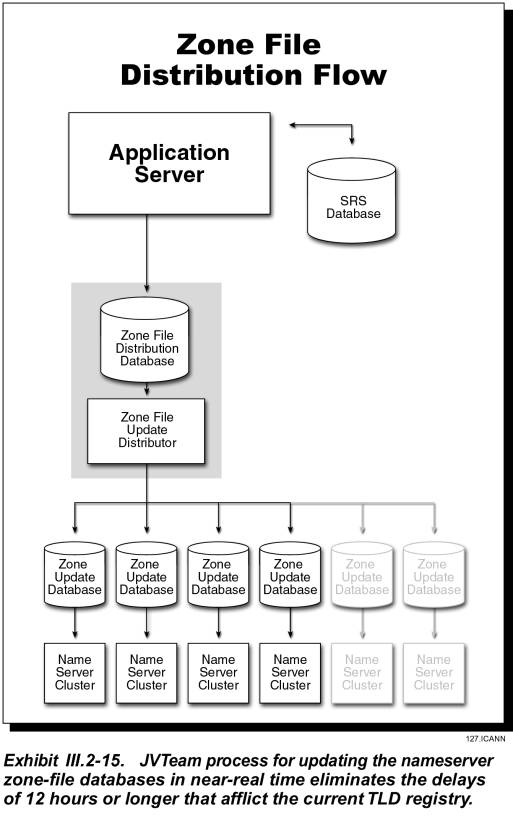

JVTeam expects to implement all applicable best-practice recommendations
contained in RFC2870 (Root Nameserver Operational Requirements).
III.2.6�������� Billing and Collection System (RFP Section D15.2.6)
JVTeam�s proven experience in successfully selecting, implementing, and operating complex Billing and Collection (B&C) systems for communications and domain-name registries and registrar services ensures our registry operator�s Billing services will be feature rich, accurate, secure, and accessible to the Registrars.
The B&C system will maintain customers� accounts, create account statements, audit and tracking information for both customers and the industry.
The fundamental goal of the system is to maintain the B&C data and create reports which are accurate, accessible, secured, and scalable.� B&C will enable detailed transaction-based charging to the customers, based on extensive resource accounting and usage data recording performed in the Registry System.� The B&C system must produce timely and accurate account statements and billing reports that are accurate, easy to understand and contain only clearly defined charges form the Catalog of services and prices. Such account statements are ultimately more economical because they are less likely to provoke costly billing disputes.
JVTeam offers a simple B&C process as depicted in Exhibit III.2-17 is based on debit accounts established by each of our registrar clients.� We will withdraw all domain registration service payments from the incurring registrar�s debit account on a per-transaction basis.� We will provide fee-incurring services (e.g., domain registrations, registrar transfers, domain renewals) for a registrar only so long as that registrar�s account shows a positive balance.� Although our system will operate in US dollars, it will be capable of supporting multiple currency conversions.� Further, the B&C system will be sufficiently flexible to adapt to different billable events, grace-period implementations, and pricing structures.
JVTeam�s B&C system will be located at the two redundant SRS data centers in Virginia and Chicago. These systems will handle the key B&C functions, including:
� Debiting and crediting registrars accounts
� Initiating low-balance notifications
� Enabling registrars to view their accounts.
� Tracking and reporting historical information
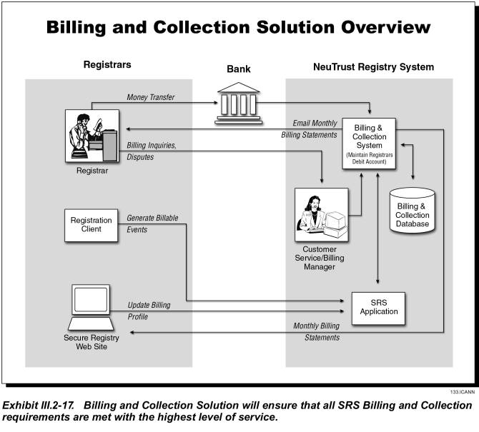
III.2.6.1����� Technical Capabilities and Characteristics
JVTeam will customize an off-the-shelf product to ensure data processing accuracy, accessibility, flexibility, and scalability to accommodate increasing transaction volumes and additional billable events.� Our finance and technical experts are experienced in customizing systems to evolve smoothly from performing simple to more complex tasks, and from small-scale to large-scale operations. We selected this solution after conducting a detailed analysis of the options for administering the registry�s B&C system. Our proposed system will:
� Meet all registry B&C requirements, including
- Generating the large amount of detailed resource-accounting information needed to support detailed usage-based charging of registrars
- Support US Dollars currency as well as currency conversions
- Support flexible queries of the Registry B&C database through an API�
- Tracking and reporting historical information.
� Be cost effective.
� Be operational within the scheduled implementation dates.
� Support multiple Top Level Domain names at varying prices.� In the case, the customer, contact, account, service catalog, and all other information will be totally separated between the multiple entities in the database.
B&C System Description
Exhibit III.2-18 illustrates the major components of the B&C system and its interfaces with other SRS subsystems.
B&C database �This database, which is separate from the Registry�s SRS database, contains the data shown in the following table.� Proposal Paragraph III.2.3 discusses the capabilities, management, administration and backup of all databases, including the B&C database.� This subsection discusses only the design aspects of the B&C database.
Transaction Processor � This processor, which responds to inputs from the external application server and from the B&C operations GUI, is the only component that has access to update the B&C database.� The transaction processor will process transactions in real-time, responding to API calls from application servers, and also will process transaction log files obtained from external servers.� The transaction processor has two main subcomponents:
� Registrar Profile Administrator�The component that responds to the registrar-administration component of the application server
� B&C Processor�The component that processes all domain registration related requests and other billable events from external servers.
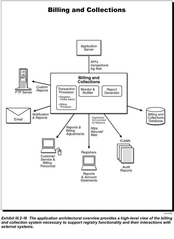
|
B&C� Database Contents |
|||
|
Primary Element |
Details |
Primary Element |
Details |
|
Catalog |
� Transaction type � Amount charged � Start date � End date �
Additional
information |
Transaction data |
� Transaction ID � Registrar ID � Transaction type � Start date � End date � Domain name � Registrant contact information |
|
Registrar |
� Registrar name � Registrar ID � Registrar email address � Registrar address � Preferred payment method � Account set-up date � Operational date �
End date |
Account history |
� Registrar ID � Amount received � Date of amount received �
Transaction
type |
|
Account Information |
� Registrar ID �
Current
Amount |
||
|
User Administration |
� User id � User role |
||
Monitor and Notifier�This component monitors the registrars� accounts for sufficient funds and monitors domain name expirations and renewals.� When it detects actionable items, it notifies the transaction processor and the registry�s Customer Service organization.
Report Generator�This component will generate monthly account statements and various reports, including annual reports.� This is also the component that Customer Service will use to generate custom reports requested by a registrar. After generating custom reports in a batch process, the report generator sends them to the FTP directory, where they are stored for the registrar to download.
B&C System Interfaces
As Exhibit III.2-18 above indicates, the B&C system will have four types of interfaces:
Application Programmer Interfaces (APIs)�that connect billing functionality with selected non-B&C functions of the registry; e.g., registrar administration, domain registration, accounting system entries, and email processes.� The APIs, which connect to the application server, will provide good query capabilities, triggers for billable events, and a means for customizing or extending B&C functionality.� The APIs will enable the B&C system to perform B&C functions in near real time; i.e., at the same time that the registry system is processing the request. The APIs will be well defined, including parameters used and resultant status codes. All error codes will be well documented, and B&C activities will be logged for tracking and audit purposes. API functions include the following:
� Validating the application using application id & password
� Accessing a registrar�s account to verify its balance and perform a financial transaction
� Adding a domain registration
� Canceling a domain registration
� Transferring a domain registration
� Requesting a custom report
� Administering a registrar�s billing profile.
GUI Client�for the B&C system�s registry operations personnel, who will use this interface for system administration and reporting functions, including:
� Establishing and administering registrar accounts
� Administering B&C functionality, including making adjustments
� Generating routine and special reports.
Secure Web-based Portal�that enables registrars to use readily available Web browsers (Netscape Navigator 4.0 or above, or Microsoft Internet Explorer 4.0 or above) to monitor their account balances and view reports over the Internet.� Using this interface, registrars can view the balance in their debit accounts and domain-registration records in detail.� Registrars are granted permissions via the database security features to access data pertaining to their own accounts, but cannot access data from other registrar�s accounts.� Registrars also are able to select the interface by which the query or report will be delivered; depending upon the type of report or query, the available interfaces can include on-screen, FTP, or email.� The interface will be via a secure network using the SRS Web Server, HTML, and an off-the-shelf reporting tool.� Features of the Web GUI include:
� Open, non-proprietary, standards-based GUI technology (HTTP + SSL)
� Economical, readily available client software for users
� Secure access
� Flexible design
� On-line help
� Consistent presentation style
� Ease of navigation, with menu-type options
� Data-entry checking.
Transaction Log Files�are automatically created by and transferred from external systems such as the application server and database systems.
B&C Procedures
�The B&C system processes data that is generated during the following three types of procedures:
� Registrar administration�The B&C system will manage the B&C profile for registrars, along with the account and contact information.
� Transactional services�Actions that trigger a B&C event.� Registrar�s requests result in �transactions� at the application level and �events� in the B&C process.�
� Non-transactional services�actions including balance forecasting, account balances.
The following tables provide details of each type of process flow.� Where they state that the B&C system sends a special notification to a registrar, it also sends a copy to the Registry�s Customer Service organization.
|
Registrar Administration |
|
|
Function |
B&C Process Flow |
|
Initial Account Setup |
� Registry receives the registrar�s Registry Service Agreement and the license fee. � Registry establishes an account in the B&C system, enters all contact information, but account status is non-operational. |
|
Operational Account Setup |
� Registry verifies registrar�s acceptability and invoices for the annual maintenance fee. � Registry receives maintenance fee payment and changes account status to operational. � Registry notifies registrar to prepay the established debit account. |
|
Debit Account Prepayment |
� Registry receives registrar�s payment, opens debit account, and credits received amount to that account. |
|
Change in B&C Profile |
� Registry receives the request. � If registry approves, it updates registrar�s B&C profile in B&C system. |
|
Credit Extension |
� Registry receives the request. � If registry approves, B&C system extends the credit. |
|
Change in Payment Methods |
� Registry receives the request. � If registry approves request, B&C system records the change. |
|
Transactional Services (NOTE: as used herein, the term �domain� refers to both domain names and name servers.) |
|
|
Transaction |
Process Flow |
|
Add Domain |
� Registrar submits �Add Domain� request to register new domain for a specified number of years � B&C system computes the fee; i.e.,� the annual fee times the requested term (years). � B&C system checks the requesting registrar�s debit account to verify that balance exceeds fee. � If balance is adequate, B&C system withdraws required transaction fee from the account; if inadequate, notifies registrar. � B&C system updates B&C database. �
B&C system notifies registrar of transaction
completion. |
|
Cancel Domain |
� Registrar submits �Cancel Domain� request to cancel a domain registration. � B&C system updates B&C database. � B&C system verifies time of request was within (5-day) grace period. � If grace period not exceeded, B&C system credits customer�s debit account with the total transaction fee. |
|
Renew Domain (Registrar Request) |
� Registrar submits �Renew Domain� request to renew a domain for a specified number of years. � B&C system computes the fee, which equals the annual fee times requested term. � B&C system checks requesting registrar�s debit account balance to verify that it exceeds required fee. � If balance is adequate, B&C system withdraws fee from account; if not, notifies registrar. � B&C system updates B&C database. � B&C system notifies registrar about the renewal. |
|
Renew Domain (Automatic) |
�
Domain-name registration expires without registrar
requesting either renewal or cancellation. �
B&C system automatically renews domain for one year
and computes appropriate transaction fee. �
B&C system checks registrar�s debit account balance
to verify that it exceeds required fee. �
If funds are available, B&C system withdraws fee from
account; if not, notifies registrar. �
B&C system updates B&C database. �
B&C system notifies registrar about the renewal. |
|
Cancel after Automatic
Renew (Registrar Request) |
�
Registrar submits �Cancel Automatic Renew� request. �
B&C system updates B&C database. �
B&C system verifies if request is within (45-day)
grace period. �
If within grace period, B&C system credits
registrar�s account with the total transaction fee. |
|
Transfer Registrar |
�
Registrar submits request to transfer domain to him. �
Customer Service confirms transfer with registrar
relinquishing domain. �
B&C system checks receiving registrar�s debit account
to determine whether balance exceeds one-year registration fee. �
If account balance is sufficient, B&C system
withdraws fee; if not, notifies registrar. �
B&C system updates B&C database �
B&C system notifies registrar that transfer is complete. |
|
Mass Updates |
�
Special transaction; registry�s Customer Service
establishes pricing and schedule and inputs data to B&C system. |
|
Custom Reports |
�
Registrar requests custom report(s). �
Customer Service establishes fee and generates report(s). �
Customer Service debits registrar�s account for agreed
fee. �
Customer Service transfers report to FTP server for the
registrar to download. |
|
Trademark Registration |
� Trademark holders will register their trademark. � B&C system will update B&C database |
|
Non-Transactional
Services |
|
|
Event |
Process Flow |
|
Annual Maintenance Fee |
� B&C system withdraws registrar�s annual maintenance fee from his debit account on annual membership anniversary. � B&C system updates B&C database. � B&C� system notifies the registrar. |
|
Low Account Balance |
� If the funds in a registrar�s debit account fall below the established limit, the B&C system emails a �Low Account Balance� notification to the registrar. |
|
Insufficient Funds |
� If the fee for performing a requested transaction exceeds the amount in the Registrar�s debit account, the transaction is not processed; instead, the B&C system emails an �Insufficient Funds� notification to the registrar. |
|
Balance Forecasting |
� The B&C system continually calculates the rate of fund depletion from each registrar�s debit account over the preceding 30 days. � Using this rate, the B&C system calculates the anticipated date when each registrar�s account will be depleted. � If the anticipated �insufficient funds� date is less than 21 days hence, B&C system emails a notification to the registrar. |
|
Account replenishment |
� Upon receipt of additional funds from a registrar, the B&C system will credit them to that registrar�s account. |
|
Monthly Statements |
�
The B&C system will prepare a detailed monthly
transaction statement for each registrar and will email it to that registrar.
Proposal Paragraph 15.2.3 describes these statements in the subsection titled
�Reporting Capabilities.� |
|
Online B&C Reports |
�
The B&C system will compile various
B&C-related reports and provide them to registrars and other appropriate
parties over the Internet. |
III.2.6.2����� Security
Proposal Paragraph III.2.9 provides extensive details about security issues, including system, network, and physical security, and including such specific issues as access control, authentication, and authorization. This sub section discusses only security provisions that are specific to B&C.� Like the overall registry system, the B&C system will implement security at the Network, System, and User levels, as follows:
Network-level Security�The primary network-level communications technology underlying the B&C system is the IP protocol.� The only interfaces that have access to the B&C system are the Secure Web GUI to monitor account status and the FTP server to download reports. A firewall forms the secure interface between our secure internal network and the untrusted Internet.� Firewalls use filters to permit or deny packet flow on the basis of the origin and/or destination of the packet�s addresses and ports.
Users who want to obtain access to the Secure Web portal that we provide to the registrars must first obtain access to the Secure Web server within the SRS.� When the user�s Web browser attempts to establish an HTTPS (secure web application protocol) session with the registry, our system initiates the SSL (secure sockets layer). �Part of the initialization sequence is a public key exchange or identification.� Once the SSL initialization is complete, it establishes a secure, encrypted channel between the user�s web browser and the registry�s web server, and exchanges digital certificates to ensure the integrity and authenticity of the session.� The use of a secure web browser/server ensures that no clear text, including passwords, is sent over the public or shared-data network.
System-level Security�Secure user login facilities ensure that Secure Web Server users are fully authorized and authenticated.� The SRS Secure Web Server presents a login menu on the user�s Web browser.� The login menu includes 20 lines of warning message stating that this is a private computer system and authorization is required for access.� The default warning message will be: �NOTICE: This is a private computer system.� Unauthorized access or use may lead to prosecution!�
When users attempt to log into the Secure Web server, they must enter their user-id and their password.� The login/password information forwarded back to the JVTeam�s Registry web server is encrypted through the secure SSL channel previously established.�
User-level Security�Every B&C system user (individual and application, external and internal) has a unique user login account on the system, with unique user-identification codes (userids) and passwords to authenticate the user and an access control list to control his access to system resources and applications.�� User profiles are set up and maintained in the database system so that users access to the B&C system is controlled by their user profile and the access privileges granted therein. JVTeam will establish and maintain well-defined security procedures for adding and deleting users and modifying their logon account, access control lists, and user profile access privileges depending on the user�s functional role.� The following subsection, �Access Privileges,� contains additional information about user roles and privileges.�
III.2.6.3����� Access Privileges
The B&C system and network employ multi-tiered access control to ensure that all B&C resources�transactions, data, etc. �can be accessed and used only by authorized users. As previously discussed, access to the proposed B&C system via the network is fully secured behind a perimeter firewall and user-id and password system, while physical access is controlled using electronic keys and palm readers. Once an authorized user gains access to the system, their privileges are control by the operating system access control lists and the database system user profile that determines what functions, system resources and data the user is allowed to access and use.� Access privileges are broadly defined and controlled for the following user groups:
� Registry employees
� Registrars
� Sponsoring Organizations of the Registry
The following subparagraphs discuss the access privileges of each group.
Registry Employees
Only internal registry staff members, using cardkeys, can gain access to the registry facility. Registry employees who are authorized to access the B&C system do so using workstations connected through the registry LAN.�� Except for the system administrators, these employees access the system using the B&C client interface, which will be established specifically for staff members to perform billing adjustments, maintenance, and related functions.
Each internal user of the B&C system is also associated with a user role that will permit or deny his access to different functions in the B&C system. The System Administrator will create roles and allow them to access certain functionality.� Initially, we expect to define user roles within JVTeam�s B&C-operations organization as follows:
� System Administrators: perform system upgrades, maintenance, and user administration.
� B&C System Administrator: configure the B&C system; e.g., user groups and their access rights, batch-process schedule, configurable business rules, etc.
� B&C System Operator: establish users, monitor back processes, provide system support, and monitor and correct billing errors.
� Customer Service: view a registrar�s billing history and collect information for the B&C manager.
� B&C Clerks: create transactions, such as invoices and collections, but not make adjustments.
� B&C Manager: create adjustments, catalog changes, and customer changes.
� B&C Database Administrator: perform mass database updates.
Registrars
Registrars have only view access to their B&C account status, account statements, and reports. They have to contact B&C personnel within the registry�s Customer Support organization for any billing adjustments, custom reports, or special arrangements.
Query Capabilities�The Web GUI will provide authorized registrars with the ability to query the B&C database for information. As previously described, to access the Web GUI, the registrar must obtain network access to the registry web server, then proceed through the identification and authentication process using a valid logon id and password.� A registrar�s access to the B&C information is limited to his own accounts; he is denied access to the information about any other registrar�s account.� The supports such standard queries/reports as:
� List of all domain names owned by the registrar
� Account balance
� Monthly account statements
� List of all domain names with renewal dates within a defined period
� Detail transaction report for defined period.
Registrars can submit non-standard queries or requests for special reports by contacting JVTeam�s Customer Service organization via email, phone, or fax.� Customer Service will place any custom reports on a secure FTP server, from which the requesting registrar can download them.
Adjustments�For billing issues or adjustments in profile or account statements, registrars must contact JVTeam�s Customer Service organization via email, phone call or fax. The B&C Manager has the capability of performing any billing adjustments or similar services requested by a registrar.
Notifications & Statements�The registry will email to each registrar a detailed monthly transaction statement, an account summary, and a detailed list of all fee-incurring charges.� In addition, the B&C system will automatically email �Low Account Balance� and �Insufficient funds� notifications to any registrar when needed.
Sponsoring Organizations of the Registry
Sponsoring organizations have view access in to some components of the B&C system. They can access aggregate reports on capacity, finance, and other functional and operational reports of the overall registry system. Some of the capacity, finance reports, procedures, and policy implementations are available to the sponsoring organization through the secure Web GUI using login id/password.� Sponsoring organizations can audit the registry on its implementation of:
� Policies
� Mission
� Permitted participants
� Capacity handling
� Accountability
� Revenue forecasts.
III.2.6.4����� Backup and Recovery
We will employ the same backup and recovery procedures for the B&C system that we use for the overall registry system. Proposal Paragraph III.2.7 describes these procedures in detail.� They include:�
� Backup to DLT Tapes will be performed daily and the tapes are stored in a secure off-site location.
� Periodic archives of history files and data, which we will also store offsite in a secure location.
If the B&C system fails (i.e., the API interface to the application returns an �Error status�), a built-in recovery mechanism will ensure against loss of transactions and data, as follows: the application server will log all undeliverable B&C transactions, with transaction identifiers, to an internal file.� After the problem is corrected, the file will be transferred to the B&C system for processing.
III.2.6.5����� B&C Audits
JVTeam will provide the infrastructure to collect all data needed for accounting and auditing reports that meet commercially accepted standards, and will provide this data to ICANN designated auditors.� Data will be available for the current fiscal year and for an agreed number of preceding years. JVTeam will assist ICANN auditors by providing all required statements and reports. Annually, JVTeam�s internal auditors will audit the registry�s B&C system, records, and supporting documentation to verify the accuracy of billing for registry services.
III.2.7�������� Data Escrow and Backup (RFP Section D15.2.7)
JVTeam will back up the databases in our data centers in Sterling, VA and Chicago, IL, and will regularly place escrow copies of the backups in secure off-site locations. These procedures are essential elements of our realistic plans for continuity of operations in the event of system failures and natural or man-made disasters.
The goal of any data backup and recovery procedure is full recovery from failures without any loss of data.� Data backup strategies handle system hardware failures (e.g. loss of a processor or one or more disk drives) by reinstalling the data from daily backups, supplemented by the information on the �before� and �after� image-journal backup files that the database creates.
The conventional strategy for guarding against loss of the entire facility because of fire, flood, or other natural or man-made disaster is to provide off-site escrow of the registry data in a secure storage facility.� Even when successful, this recovery strategy does not prevent the loss of a certain volume of transactions between the time the data was backed up and the occurrence of the disaster. Users are subject to denial of service during the time required to recover the data-center database and/or reestablish operations at an alternate disaster-recovery site.� Relocating the data center normally requires at least 24 hours, and the escrowing of backups often is done only weekly, meaning that a disaster could result in substantial loss of both services and data.
JVTeam�s backup solution goes a step further. We propose two co-active SRS data centers, each capable of handling the entire workload should a major system failure or natural or man-made disaster occur at the other. The transactions from each data center are replicated in real time to the other over a redundant high-speed Virtual Private Network (VPN) telecommunications links. Each SRS data center also conducts independent backups, as described in the following paragraph. Since the two SRS data centers are co-active, our backup strategy maintains continuity of operations and enables full recovery of all transactions, even in the event of multiple hardware failures.�
III.2.7.1����� Frequency and Procedures for Backup of Data�
Each co-active data center independently implements a zero-downtime/zero-impact incremental data backup each day, and a full data backup weekly. We place escrow copies of the backup tapes in a secure off-site storage facility operated by a third party whose business is data escrow. We copy static data (e.g., the operating systems, BIND software, applications software) to CD-ROMs for quick reload, should that become necessary.� We back up to DLT tape any dynamically changing files (e.g., log files vital to system maintenance and operation, database files, database-journal files, software configurations). Weekly, we perform full-system backups to DLT tape of all databases identified in Section III.2.3 (SRS DB, Whois, Billing).
Each data center uses on-line zero-downtime/zero-impact,
backup procedures that include the following 4 steps:
1.
The database
is put into backup mode to guarantee a consistent version of the data on the
snapshot copy that is written to a RAID disk array for subsequent
(slower-speed) copying to tape. While the database is in backup mode,
the XRP, Whois, and Billing applications continue to function and to access the
data.� The database normally is in
backup mode for only about 5 to 10 minutes.
2.
The backup
software writes the data to the RAID disk array.
3. The backup software, which is located on a backup server independent from the application servers, creates the backup DLT Tape copy from the snap shot copy on the RAID disk array.
4. When the backup is finished, the DLT Tapes are transported to the secure escrow facility.
III.2.7.2����� Backup Hardware and
Software Systems
Exhibit III.2-19 depicts the SRS data centers� backup and recovery hardware and software. Each data center�s system includes two backup servers with DLT robotic tape libraries.� The data backup system uses the DLT IV data cartridge and the DLT 5 data format. To achieve zero-downtime/zero-impact backup, we use a RAID disk array and a high-speed-fibre, channel-bridge interconnect to the robotic tape libraries. The backup server copies not only the database-server�s backup files to the disk array, as discussed in the 4-step process already described, but also the backup files of the cluster servers. During the few minutes this process requires, applications still have access to the cluster servers and database server.� Then the backup server copies the files to the DLT Robotic tape device. This approach ensures that we can meet our Service Level Agreements (SLAs).
Due to the criticality of the database, the JVTeam proposes a fully redundant, fault-tolerant database management system. We will configure the database system as two independent database servers � primary and backup � with synchronous replication using two-way commits to maintain database synchronization. If one database server fails, the database system is sized so that the second server can process the entire load without degradation while the primary server is restored to service.
We will transport both daily incremental backups of dynamically changing data and the weekly full backup to a secure escrow agent to be selected with the concurrence of ICANN.
III.2.7.3����� Procedures for Retrieval of Data and Rebuild of the Database.
We maintain copies of the DLT tapes holding incremental data backups in a three tape rotation:
� One DLT backup tape is in transit to the secure escrow facility.
� A second DLT tape is in storage in the secure escrow facility
� The third DLT tape is in the data center for reuse.
The full backup tapes are maintained in a 2-tape rotation, with one tape at the secure escrow facility and one at the data center for reuse. A copy of the static-data CD ROMs for the operating systems and applications are also maintained at the escrow facility.
Should the primary database server experience a catastrophic crash that necessitates a lengthy recovery process, data-center operations continue seamlessly on the backup database server that replicates all the data in the primary.� After the failed database server is repaired, we recover its data using the full backup tape and incremental backup tape that is retrieved from the escrow facility. We first restore the full backup files; then, the incremental files. We then synchronize the recovered database to the primary database. This procedure recovers the database to the last complete transaction processed by the primary database.
This backup procedure enables JVTeam to meet the service level agreements required for continuous availability and near-zero unplanned downtime, thereby improving the stability of the Internet, enhancing public confidence, and improving customer satisfaction.
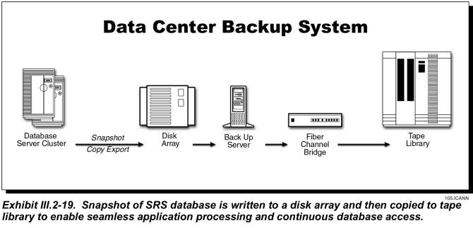
III.2.8�������� Publicly Accessible Look Up/Whois Service (RFP Section D15.2.8)
JVTeam proposes a Whois service that will eliminate problems associated with the current multiple Whois systems.� The most serious of these problems is a genuine threat to the stability of the Internet: the possibility that relying on Whois information that can be at least 12 hours out of date could result in an erroneous change relating to the domain name of a large Internet site that performs millions of dollars worth of e-commerce transactions daily.
Whois is a database of information about Internet domain names.� JVTeam�s proposed registry will maintain a state-of-the-art, real-time Whois service that will make this information available on the common Whois port (Port 43).� Our registry will store all information relating to Whois data entities, including contact and authentication data.�
The Whois service is intended as a directory service for registrants, as well as for any other individuals and businesses that want to query details of domain names or related data stored in the registry.� Our Whois data will be available in both conventional and machine-readable format, facilitating automation.� Further, the level of information displayed will be configurable.
Registrars will provide the front-end web interface to the Whois directory.� Because this interface will be a simple wrapper around the registry�s Whois service, the registrars will have complete control over the service�s look and feel and branding.� With this control, registrars will be able to comply with the privacy restrictions enacted by the countries where they operate.
Problems with Current TLD Whois Service
The current .com/.net/.org Whois service has caused many problems for both registrars and registrants.� The system has confused registrants, and its inherent problems have increased costs (and risk) to registrars, who had to provide manual processing or recovery from failures in automated processes.� Inherent system problems include the following:
� Different protocols used (i.e., not all registrars use Whois on Port 43)
� Different fields exposed
� Different formatting of data
� Timing inconsistencies (regarding adding, deleting, transfer of registrar, etc)
� Not real time (Whois is updated only every 12 hours)
� No standard machine-readable format
As a result of these system problems, records in a registrar�s Whois can contradict those in the registry�s Whois, or records in two registrars� Whois services can contradict each other.� The most serious problem with the current system and an issue of serious concern relating to the stability of the Internet is that a gaining registrar uses the Whois service to determine if a Transfer of Registrar request is authentic.� If a mistake is made in the transfer of registrar, an incorrect owner could redelegate a domain name (or change ownership), potentially bringing down a large Internet site performing millions of dollars of e-commerce transactions per day.
Benefits of Proposed Solution
The system problems cited in the preceding paragraph could theoretically be solved with stronger enforcement of technical standards, such as protocols, fields, and data formatting.� JVTeam�s proposed solution centralizing the Whois data and providing access via registrars is more pragmatic and will solve all current problems.� Our solution would provide:
� Central location for all authoritative TLD data
� Standard protocol accessible over port 43
� Consistent format (fields, formatting, etc) for all registrars
�
Machine-readable
format (promotes automation)
� Elimination of �timing� problems when modifying entities
� Real-time update
� Extensible field capability.
III.2.8.1����� Whois Service Functional Description
The Whois service will accommodate queries regarding the data entities listed in the following table
|
Entities |
Fields |
|
Domain names |
Attributes (Status) Associated nameservers Associated registrar Associated registrant data |
|
Nameserver |
Attributes (Status) Associated IP addresses Associated registrar Associated registrant data |
|
IP Address |
Attributes (Status) Associated nameserver Associated registrar Associated registrant data |
|
Registrar List |
Registrar name |
|
Registrars |
Registrar name Registrar contact details Registrar URL (Home page) Registrar Whois URL (Web Port 80) Registrar Whois URL (Port 43, if applicable) Attributes (Status) |
Machine-Readable Format
JVTeam�s standardized Whois format will facilitate automated parsing of Whois information
Because the viewable data could be modified over time (e.g., new fields could be added), a more robust and formalized encoding mechanism is needed to provide the non-Registrar community reliable automated access to Whois data.
For example, an organization tracking trademark infringement might want to acquire the Whois data, automatically parse it, and store it in a tracking system.� To accommodate such organizations, which will not have access to the XRP protocol, the Whois information must be presented in a formal, extensible way that is compatible with automated processing.� To accomplish this, we will present the Whois data in an open, standard, XML-based, machine-readable format that we designate as the XWP (eXtensible Whois Protocol).� The information accessible via the XWP is inherently tied to the XRP (eXtensible Registry Protocol) data requirements, and thus, will be part of the same standardization process.� Just as we will do with the XRP, JVTeam commits to submitting the XWP to an industry standards body for adoption and future modification according to that body�s normal procedures.
Extensible-Field Capability
In the spirit of providing advanced services to the registrar community, JVTeam will introduce the ability for registrars to use XRP to add customized fields to a record in the registry database.� These fields will appear in an �additional information� section of the Whois data.� The maximum number of custom fields allowed per record is yet to be determined.
The extensible-field capability will eliminate the need for registrars to store additional information in their own local database, then combine it with the registry Whois information when they present it to end users.� The proposed capability will also ensure that end users will view the same information no matter which registrar they use to retrieve Whois data.
All custom fields would appear in a special additional information section at the end of the uniform Whois data.� In human-readable form, the customized fields could appear as follows:
Additional Information:
���
<name>: <value>
���
<name>: <value>
��� �
In XWP format, the customized fields could appear as
follows:
<additional>
���
<custom name=�xxxxxx� value=�yyyyyy�/>
���
<custom name=�xxxxxx� value=�yyyyyy�/>
</additional>
JVTeam intends to provide extensible-field functionality during any Sunrise period to support publishing of trademark (and associated) information.
Bulk-Access Program
Much of the load placed on the current .com/.net/.org Whois service is caused by automated programs mining for data.� Because Whois data is publicly accessible, this will always occur; however, JVTeam proposes to provide a data mart. that limits the recipient�s conditions of use.
The proposed data mart bulk-access program would:
� Reduce the load that data mining currently imposes on the core Whois service
� Contractually limit subscribers in the ways they can use the data
� Provide a source of revenue to fund advanced service levels
� Reduce the incentive to download entire database without legitimate purpose
� Provide the entire database in a format that facilitates such data mining as conducting trademark searches, compiling industry statistics, and providing directory services.
The registry will make the Whois data available to registrars, who will conduct the actual bulk-access program.� Data will be exposed only within the privacy restrictions described in the following subsection.
Privacy Restrictions
A number of countries
have enacted privacy laws (e.g., the European Union Privacy Directive) that restrict the information that can be
presented in the Whois service.� Under
the terms of its licensing agreement, JVTeam will bind registrars to comply
with all applicable privacy laws while providing Whois services.
Each registrant
account will have a privacy attribute that can be set to one of the following
levels:
�
Unrestricted�Complete registrant details displayed
�
Restricted�Registrant name and address displayed
�
Private�No Registrant details displayed
Registrants in
countries that have enacted privacy laws can select the privacy level permitted
under law.� No matter which level they
select, such details as the delegated nameservers and associated registrar will
still be visible.
Private information will be released only under court order or the direction of some other authority that has legal jurisdiction to demand such release.
Restricting
private data will not create problems for registrars� �Transfers of Change of
Ownership� transactions because these operations will be conducted using the
centralized authentication mechanism.
III.2.8.2 ���� Whois System Architecture
JVTeam will deliver a Whois service that incorporates semi-real-time update, scalable infrastructure, and multiple layers of redundancy.�� We will initially deploy the Whois servers at the two co-active SRS data centers shown previously in Exhibit III.2-1.� The software architecture will enable us to deploy Whois infrastructure to any number of additional JVTeam data centers.� As the registry grows, we will deploy additional Whois infrastructure as appropriate to increase geographic dispersion, enhance the level of service in particularly geographic regions, and reduce the load on the SRS data centers.� We are willing to negotiate with ICANN about adding and siting additional Whois services.
Exhibit III.2-20 illustrates the Whois architecture.� At each Whois site, incoming queries are distributed by a load balancer to a cluster of Whois servers, which are, in turn, connected to a backend database cluster.� This configuration will provide both redundancy and scalability through the addition of servers to either cluster.
Each Whois server will cache common requests in memory and query the back-end database cluster only on a cache miss.� We can configure the duration that Whois information is cached before being deleted (e.g., 10 minutes); after deletion, the server must query the database for the information.� Each Whois server will be configured with at least 2 GB of high-speed memory, sufficient to hold at least one million of the most commonly queried Whois records.�
Exhibit III.2-21 depicts the update of the Whois databases.� As the SRS database is updated, the system will also update the Whois distribution database server in real time.� This database will be replicated to the Whois databases within defined service levels (e.g., 10 minutes).� Replication between data centers always occurs over a VPN or a dedicated link, and the registry will digitally sign update packages.�
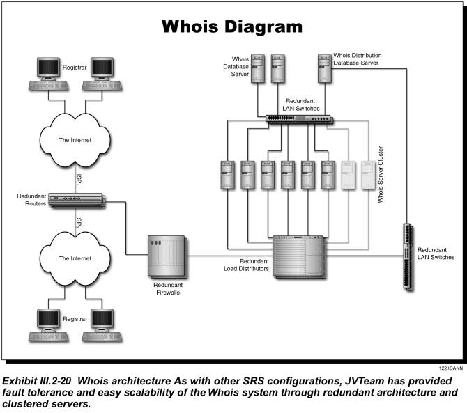

The proposed Whois service offers the following benefits:
� Service can be scaled by adding servers to each Whois cluster
� Databases can be scaled by adding machines to each database cluster
� Service can be scaled by deploying Whois infrastructure to additional data centers
� Inherent redundancy ensures high availability
� Update process ensures near-real-time availability of the latest information
�
Caching of common queries provides superb response
time.
III.2.8.3 ���� Network Speed and Proposed Service Levels
The large volume of Whois queries places a significant network-connectivity burden on the registry.� Based on the assumption that each Whois query will generate approximately 10 Kbits of network traffic, we will use the following engineering guidelines for provisioning bandwidth:
� Initially, we will provide 25 Mbits per data center.� The total of 50 Mbits will support approximately 5,000 queries per second (approximately 430 million requests per day).
� As the volume of registrations grows, we will extend the service at a rate of 10 Mbits per one million domain-name registration records under our management.� For example: when the registry manages 20 million domain names, we will dedicate 200 Mbits of Whois bandwidth, which will support nearly two billion Whois queries per day.
These guidelines will be compared with actual usage data and adjusted accordingly.
We will engineer the Whois service to provide the following average service levels, and are willing to negotiate service levels:
� 400 million queries per day (90% cache hits, 10% cache misses, which must be forwarded to database file).� We will increase this query-service demand based on the total number of domain name registrations managed by the registry, as previously discussed.
� 200-millisecond latency for cache hits (after the request reaches the data center).
� 500-millisecond latency for cache misses (after the request reaches data center).
We will configure the Whois service to limit connections based on the following criteria:
� 1000 queries per minute from any single IP address
� 20,000 queries per minute for requests originating from designated registrar subnets
� An �acceptable use� policy that we will negotiate with ICANN and the registrar community.
We will scale the exact number of Whois and database servers deployed in each cluster and at each data center to maintain the specified service levels.
III.2.9�������� System Security (RFP Section D15.2.9)
JVTeam is currently operating successful data centers for various telecommunications and domain-name� registry services.� This experience has familiarized us with security risks, as well as with the most current and effective means of thwarting such risks.� ICANN can be assured that our comprehensive security provisions will protect the TLD infrastructure, operations, and data.
Shared Registration System (SRS) and nameserver data centers are subject to a wide range of security threats, including hacking, break-ins, data tampering, denial of service, and physical attacks against the facility.� The recent denial-of-service attacks against important government and dot-com sites point to the technical capabilities of some hackers and the lengths to which they will go to attack the Internet community.� Further, because the Registry will contain proprietary data from competing registrars, security procedures must incorporate user-authentication procedures that ensure that each registrar�s files are available only to its own personnel.
Failure to address
these security threats creates the risks of unscheduled down time and the
disruption or denial of services.
This section describes
system-security features that we will implement in our networks, servers, and applications
for the SRS data centers and nameserver data centers.
III.2.9.1����� System Security
JVTeam offers ICANN comprehensive system security for our networks, servers, applications, and customer support services. Our security architecture is a policy-based, multi-tiered structure based on industry standards and on evolving new IEFT standards for registry-to-registrar security and secure DNS. Our solution integrates the following security features to provide assurance that multiple security threats or attacks will be unsuccessful:
� Perimeter protection for Whois and DNS applications
� C-2-level controlled access at the server operating systems
� Applications-level security features for XRP, Billing & Collection, and customer-service applications
� Connection security
� Data security
� Intrusion detection
� User identification and authentication
� Continuity of operations
� Physical security.�
Exhibit III.2-22 depicts our implementation of these security features to prevent system break-ins, data tampering, and denial-of-service attacks.

III.2.9.1.1���� Shared Registration System Data Center Security
Network Security
Edge routers, firewalls, and load balancers provide perimeter protection for the data-center network and applications systems, guarding against unauthorized access from the Internet.
� Edge Router�The first security layer is the edge routers, which employ IP-packet filtering.�
� Firewall�The second layer of perimeter security is a firewall that provides policy-based IP filtering to protect against system hacks, break-ins, and denial of service attacks. The firewall also includes network-based intrusion detection to protect against Internet hackers.
� Load Balancer�The third layer of protection is provided by load balancers within each data center.� Load balancing protects our application servers from common denial-of-service attacks; e.g., SYN floods, ping floods, and �smurfs� attacks. Security policies can be based on any combination of source address, destination address, and protocol type or content.
� Virtual Private Network (VPN)�The registry network will use VPN technology to perform database updates at the nameservers, network-based backup/restore, remote system/network management, and system administration.� Our goal is to operate the nameserver data centers sites in a �lights out� (unmanned) mode. VPN technology achieves secure data transfer through encrypted data-communications links.
Server Security
The SRS operating systems provide C-2-level access protection through a user login procedure and through file-level access-control lists. These access-control mechanisms perform the following functions:
� User-account security, which establishes the access capabilities of a specific authenticated user. After authenticating a user, each application�s security-data tables control access to information.� Access is based not only on user-id, but also on the type of application being used; e.g., XRP, Billing and Collection, etc. The application server uses user-id to provide precise control of access privileges to � and uses of (read, write, execute) � all system resources: screens, menus, transactions, data fields, database tables, files, records, print facilities, tape facilities, software tools, and software executables.
� Group-level security, which establishes the access capabilities of all users within a specific group.� All users belong to one or more access-control groups.� Access control is identical to that for individual users.��
� System Administration-level security, which restricts access to system administration tools, including the ability to change resource-access privileges. SRS system-administration staff use dedicated links on an internal LAN/WAN to access administrative functions that are off-limits to others.� There is no external access to this LAN.� All sessions require user identification by user name and password; access control lists determine what resources a user or user group is allowed to access and use.
The SRS operating systems will perform security-relevant logging functions, including:
�
User Login�Whenever a user login is attempted,
whether successful or not, the event is logged.� The logged information includes the user-id, time, and device
requested.
�
User Accounting��User Accounting� logs every
process executed by every user.� The
output includes date and time, user-id, point of entry, process, resources
accessed, and result of the operations.��
This log may be selectively viewed for actions performed by a specific
user or users.
�
System Logging�This inherent, configurable
logging capability permits monitoring the kernel, user processes, mail system,
authorization system, etc.� In addition,
the operating system detects when file-access privileges have been changed, and
also audits the use of telnet, finger, rsh, exec, talk, and similar operations.
The following provisions apply to passwords:
� Passwords must be at least six alphanumeric characters in length.� At least one character must be alphabetic; at least one must be a numeric or punctuation character.
� If a user forgets his/her password, the system administrator verifies the user�s identity, and then provides the user with a temporary password that enables him/her to log on only to the site where users create their own new passwords.
� Passwords are valid only for a pre-established duration (typically 90 days, but re-configurable).� Prior to password expiration, the system instructs the user to create a new password.�
� When a user changes his/her password, the system first re-authenticates the existing password, and then requires the user to verify the new password before accepting the change. The system will not accept, as a user�s new password, either of that user�s two most recent passwords.
� Passwords are encrypted and stored in an inaccessible system file.�
Application Security
Each SRS application will have its own set of security processes and technical controls. The SRS applications that interface with the registrars (e.g., the XRP and the Secure Web Customer Service portal) employ the SSL (secure sockets layer) protocol element that uses public-key exchange and RC4 encryption.� Public services (e.g., Whois, DNS queries, and the public Internet Web portal) rely on the previously discussed network perimeter-security devices � edge routers, firewalls, and load balancers � to protect the internal LAN and applications servers.
� XRP Applications Security�JVTeam�s XRP server authenticates against a series of security controls before granting service, as follows:
1. The registrar�s host initiates a SSL session with the XRP server
2. The XRP server receives the registrar�s private key with the incoming message and authenticates it against the registrar�s public key, which is stored in the registry�s XRP server.�
3. After the XRP server verifies the key exchange, it completes the SSL initialization to establish a secure, encrypted channel between itself and the registrar�s host computer.� This secure, encrypted channel ensures the integrity of the registrar�s session with registry applications.
4. In combination with completing the SSL connection, the XRP server authenticates an X.509 digital certificate to verify the registrar�s identity. Digital certificates are maintained in the SRS authentication server database.�
5. The registrar logs on to the XRP server using a userid and password that determines access privileges.� We will provide each registrar with multiple userids and password pairs, so that each can establish its own group of authorized users.
� Whois Application Security�Although any Internet user has read-only access to the Whois server, JVTeam�s perimeter-security mechanisms�edge routers, firewalls, and load-balancers�will protect it against denial-of-service attacks. A designated registry administrator performs common database-administration tasks on the Whois database, including monitoring its performance.
� Nameserver Security�Just as they have with the Whois servers, all Internet users have read-only access to the nameservers.� Similarly, the edge router, firewall, and load-balancers protect the nameservers as they do the Whois servers.
� Secure-Web Customer-Service Portal�The secure-web customer-service portal uses the same security mechanisms employed by the XRP server; namely, SSL session encryption, digital certificates, and userid and password between the SRS secure web server and the registrars� Web browsers. In addition, e-mail messages are encrypted with a Pretty Good Privacy (PGP) public-key-infrastructure implementation. Digital certificates are maintained in the authentication server.
The following table summarizes the benefits of each security mechanism that we employ at the data centers to prevent system hacking , break-ins, and denial-of-service attacks..
|
Security System |
Features and Benefits |
|
Server
Operating-System Security |
|
|
User ID and password;
file-level access-control lists |
Ensures that the user can
access authorized functions, but no others, and can perform only authorized
operations within these functions.�
For example, the registrar of a registered domain name is authorized
to query it and then renew or cancel it or change its nameservers, but cannot
query domain names held by other registrars. |
|
Database
Security |
|
|
User ID and password;
user profiles |
�
Limits database access to pre-authorized users. �
Retains the last two passwords and disallows their usage. �
Rejects simultaneous sessions by an individual user. �
Stores user profiles. �
Limits access rights to database objects and functions to
a specified user or user group. �
Rejects unauthorized access attempts.� Automatically revokes identification codes
after a pre-established number of unsuccessful attempts. �
Provides a non-technical user interface to facilitate the
on-line administration of user privileges. |
|
Application
Security |
|
|
SSL v3.0 protocol |
HTTPS encryption ensures
that messages between the registry and registrars can be read only by the
intended receiver. |
|
Digital signatures |
Issued by an X.509
authentication server, digital signatures ensure that the incoming data
actually has come from the purported sender, and also provide
non-repudiation. |
|
User id and password |
Ensures that the user can
access authorized functions, but no others, and can perform only authorized
operations within these functions.�
For example, the registrar of a registered domain name is authorized
to query it and then renew or cancel it or change its nameservers, but cannot
query domain names held by other registrars. |
|
Network
Security |
|
|
Router |
Permits only DNS UDP/TCP
packets to enter the name servers, thus isolating the system from most
potentially damaging messages. |
|
Firewall |
Guards the secure TLD LAN
from the non-secure Internet by permitting the passage of only packet flows
whose origins and destinations comply with pre-established rules. |
|
Intrusion Detection |
Detects intrusion at the
LAN level.� Displays an alert at the
SRS network operations center workstation and creates a log entry. |
|
Load Balancer |
Implements security
policies to prevent denial of service attacks; e.g.,� SYN floods, ping floods, and �smurfs� |
|
Virtual Private Network |
Provides secure network
for updating nameservers, remote system administration, remote
backup/recovery, and network/system management. |
III.2.9.1.2 ��� Nameserver Data Center Security
The JVTeam�s approach to nameserver security is a subset of the security mechanisms we employ at the SRS data centers. Nameserver data center security also relies on multi-layer perimeter protection, controlled access, enforcement of applications security features, and strong physical security protection.
Network Security
The same mechanisms used for the SRS data center are employed at the Zone Nameserver data centers. Edge routers and firewalls provide perimeter protection for the data-center network and applications systems, guarding against unauthorized access from the Internet.
� Edge Router�The first security layer is the edge routers, which employs IP-packet filtering to allow only DNS UDP/TCP packets to pass into and out of the perimeter network.�
� Firewall�The second layer of perimeter security is a firewall that provides policy-based IP filtering to protect against system hacks, break-ins, and denial of service attacks. The firewall also includes network-based intrusion detection to protect against Internet hackers.
� Load Balancer�The third layer of protection is server load which protects our application servers from common denial-of-service attacks; e.g., SYN floods, ping floods, and �smurfs� attacks. Security policies can be based on any combination of source address, destination address, and protocol type or content.
� Virtual Private Network (VPN)�The registry network will use VPN technology to perform database updates at the zone nameservers, network-based backup/restore, remote system/network management, and system administration.� Our goal is to operate the zone nameserver data centers sites in a �lights out� (unmanned) mode. VPN technology achieves secure data transfer through encrypted data-communications links.
Server Security
The Zone Nameserver operating systems provide C-2-level access protection for remote system administration through a user login procedure and through file-level access-control lists. These access-control mechanisms perform the following functions:
� User-account security, which establishes the access capabilities of a specific system administration authenticated user. After authenticating the user, the operating system�s access control lists control access to information.
� System Administrator level security restricts access to system administration tools, including the ability to change resource-access privileges. Nameserver system-administration staff use dedicated links on an internal LAN/WAN to access administrative functions that are off-limits to others.� There is no external access to this LAN.� All sessions require user identification by user name and password; access control lists determine what resources a user or user group is allowed to access and use.
The Zone Nameserver operating systems will perform security-relevant logging functions, including:
�
User Login�Whenever a user login is
attempted, whether successful or not, the event is logged.� The logged information includes the user-id,
time, and device requested.
�
User Accounting��User Accounting� logs every
process executed by every user.� The
output includes date and time, user-id, point of entry, process, resources
accessed, and result of the operations.��
This log may be selectively viewed for actions performed by a specific
user or users.
�
System Logging�This inherent, configurable
logging capability permits monitoring the kernel, user processes, mail system,
authorization system, etc.� In addition,
the operating system detects when file-access privileges have been changed, and
also audits the use of telnet, finger, rsh, exec, talk, and similar operations.
Application Security
The zone nameserver essentially enables the public, via the Internet, to make DNS queries. Public services, such DNS queries, rely on the previously discussed network perimeter-security devices � edge routers, firewalls, and load balancers � to protect the internal LAN and applications servers.
III.2.9.2����� Physical Security
JVTeam vigorously enforces physical-security measures, controlling all access to our facilities.� Throughout normal working hours, security personnel stationed at each building entrance verify that employees are displaying proper identification badges and control access by non-employees.� Non-employees must sign in to gain entrance; the sign-in books are stored for a period of one year.� If the purpose of his/her visit is found to be valid, the non-employee is issued a temporary badge; otherwise, he or she is denied entrance.
At all times while they are in the facility, visitors must display their badges and must be escorted by a JVTeam employee.� We also strictly enforce the policy that employees must wear their badges prominently displayed at all times while in the facility.
During off-hours (6:30pm to 6:30am and all day on weekends and major holidays), individuals must use the proper-electronic key cards to gain access to the building.� We issue electronic-key cards only to employees who need access for business purposes.� Further, any room housing sensitive data or equipment is equipped with a self-closing door that can be opened only by individuals who activate a palm-print reader.� Senior managers establish the rights of employees to access individual rooms, and ensure that each reader is programmed to pass only those authorized individuals.� We grant access rights only to individuals whose duties require them to have hands-on contact with the equipment housed in the controlled space; administrative and customer-service staffs normally do not require such access.� The palm readers compile and maintain a record of those individuals who enter controlled rooms.�
In addition to being stationed at building entrances during normal working hours, on-site security personnel are on duty 24 hours a day and 7 days a week to monitor the images from closed-circuit television cameras placed strategically throughout the facilities.
The following table lists salient facts about our physical-security mechanisms.
|
Physical Security |
Remarks |
|
Security guards |
Physically prevent
intruder access; verify employee badges |
|
Closed-circuit
video-surveillance cameras |
Extend capabilities of
security guards; maintain access records |
|
Intrusion-detection
systems |
Provide audible and
visual alarms to notify security personnel in the event of unauthorized entry |
|
Identity badges |
Permanent badges for
employees; easily recognizable temporary badges for visitors |
|
Sign-in registers |
Maintained as permanent
records for at least one year |
|
Electronic key badges |
Control physical access
during off-hours; maintain access records |
|
Palm readers |
Restrict physical access
to mission-critical rooms within our facilities; maintain access records |
|
Self-closing doors |
Restrict physical access
to mission-critical rooms within our facilities |
III.2.10������ Peak Capacities (RFP Section D15.2.10)
JVTeam proposes a highly scalable Shared Registration System (SRS) and nameserver systems that are initially sized for a peak load of three times the average projected workload. The peak load capacity and built-in scalability of the registry system architecture ensures ICANN that adequate capacity is available during initial peak-usage periods, and that as usage grows over the life of the registry operations, the SRS system infrastructure can scale up smoothly without service disruption.
To avoid creating bottlenecks for SRS, Whois, and nameserver services, JVTeam will engineer for peak usage volumes.� In addition, JVTeam will deploy redundant co-active SRS data centers a network of nameserver data centers that are sized to handle the projected initial peak volumes. Subsequently, we will add additional zone nameservers to handle the anticipated growth. Our SRS, Whois, and nameserver architecture are designed with highly scalable server clusters and connected through networks that can be smoothly scaled up without disrupting the system.� Expansion provisions include the following:
� Servers scale from Intel SMP machines to high-end RISC SMP database platforms with shared-memory architectures
� Server processors scale from 2-way to 6-way SMP for the Intel machines, and from 2-way to 32-way SMP for the high-end RISC database machines
� The number of servers in a cluster which uses cluster management software scales from 2 to 32 to give near-linear processing scalability
� The number of servers in a cluster that does not use cluster management software can conceivable scale beyond 32 servers
� The external telecommunications-network connectivity to the SRS and nameserver data centers scales from dual T-3 to quad T-3 to hex T-3 connectivity and more as a function of the SRS transaction load and the Whois and DNS query loads
� The internal SRS and nameserver LANs consist of a switched Gigabit Ethernet backbone fabric with extensive port expandability
This subsection describes the peak capacities of the SRS, Whois, and nameserver subsystems in terms of the network, server, and database platforms initial sizing and scalability. JVTeam central backup/recovery systems, escrow systems, system/network management, and system administration systems are enterprise strength hardware and software platforms that can easily handle these management and administrative functions throughout the entire registry operations lifespan. Additional desktops/workstations can be added to accommodate growth in staff and registry workload as usage increases and the registry infrastructure grows. Our maintenance support, help desk, and technical support functions are staffed for the initial peak usage period, and staff can be increased to handle workload surges caused by registry marketing and promotional events.�����
III.2.10.1�� SRS Peak Capacity
The SRS provides the core subsystems that handle registrar transaction based services, including XRP processing, billing and collection, Secure Web portal, and backend database system services. This subsection describes the SRS subsystems peak capacity in terms of the initial sizing and scalability of the network, server, and database platforms.
Network
The XRP average steady-state transaction load is projected to be 350 transactions per second (tps), or more than 30 million transactions per day.� Since peak transactions are six times the average, we designed for a peak transaction load of 2100 tps. The average transaction size is 5,000 bits, which translates to a required telecommunication capacity of 10.5 MBPS.� The external communication-network connectivity to the Internet is initially sized at two T-3 Internet Service Provider (ISP) 45-MBPS local-access links, for a total of 90 MBPS to handle XRP transactions and Whois queries.� The registry�s Virtual Private Network (VPN) between the sites is two T-1 1.544 MBPS.� The VPN handles zone-database updates, server backup/restore, system/network management, and system-administration functions.�
Server Clusters
The XRP-server cluster and the associated applications-server clusters are front-ended with load balancers that distribute the transaction-processing workload across the servers in each cluster. Distribution algorithms include least connections, weighted least connections, round robin, and weighted round robin.
The XRP-server and applications-server clusters are initially sized to handle six times the projected steady-state workload, or 2100 peak transactions per second.� The processing capacity can grow linearly by adding additional servers to the cluster. The total system capacity is a cluster size of 32 SMP 8-way RISC servers.�
The Billing and Collection system is sized to handle 350 peak transactions per second, because not every XRP transaction results in a billable service.
Database System
The database system consists of dual high-end RISC machines, each with 2- to 32-way SMP scalability. The initial processing capacity of the database system is 4-way SMP, sized in terms of the Transaction Processing Council (TPC) C On-Line Transaction Processing (OLTP) benchmark of TPC-C 2500 transactions per second (tpsC).
The database system can grow to handle eight times the initial projected volume of transaction loads. JVTeam will closely monitor system usage, and will scale the database capacity correspondingly.
III.2.10.2�� Whois Peak Capacity
A large percentage of the load on the current registry�s Whois server is caused by data mining.� JVTeam will increase network bandwidth and add high-performance database capabilities to the Whois-service infrastructure.� Our proposed bulk-access services will reduce the Whois load by as much as two-thirds.� This subsection describes the Whois-subsystems peak capacity in terms of initial sizing and scalability of the network, server, and database platforms.�
Network
The peak Whois transaction rate is estimated to be 5,000 queries per second, with an estimated packet size of 10,000 bits. This produces a maximum load of 50 MBPS.� Initially, we will provide communication-network connectivity for Whois queries between the Internet and each data center as two T-3 Internet Service Provider (ISP) local-access links.� Although these links initially will not be used at full capacity, they ultimately can carry 90 MBPS per data center before we upgrade to larger links.
Whois Server Cluster
Our Whois server cluster is front-ended with load balancers to distribute the transaction-processing workload across the servers in each cluster. Distribution algorithms include least connections, weighted least connections, round robin, and weighted round robin.
The Whois server cluster is initially sized to handle three times the projected steady state workload, or 5000 peak transactions per second.� To improve query response time and lighten the load on the database, the Whois servers cache frequently accessed domain names.
The processing capacity can grow linearly by adding additional servers to the cluster. The total system capacity is a cluster size of 32 SMP 6-way Intel servers.� JVTeam will closely monitor Whois usage and will increase the system�s capacity to accommodate increasing demand.
Database System
Behind the Whois servers are dual mid-range RISC machines, each with 2- to 8-way SMP scalability.� Initial processing capacity will be 4-way SMP at 500 tpsC, scalable to 1000 tpsC.� (tpsC is Transaction Processing Council (TPC) On-Line Transaction Processing (OLTP) benchmark C workload.)
JVTeam is implementing a Whois bulk-load data-mart service that will enable the registrars to provide their customers with OLTP bulk query services for data mining of domain names.
III.2.10.3�� DNS-Query Peak Capacity
During the initial land rush period when registrars are marketing the new TLD domain name extensions, DNS query traffic is expected to be moderate because of less caching further down the DNS hierarchy.� Moreover, the query load won�t approach current .com/.net/.org levels until more than five million names are registered.
JVTeam�s registry handles DNS queries at the nameservers.� This subsection describes the nameservers� peak capacity in terms of the network, server, and database platforms initial sizing and scalability.� JVTeam�s design will easily scale as load increases.�
Network
JVTeam anticipates a peak load of 10,000 DNS queries per second at each nameserver data center, and estimates the average query-package size to be 1,600 bits. This load produces a required telecommunications-network bandwidth for DNS queries of 16 MBPS.� To provide this bandwidth, we will provision two T-3 access links to the Internet at each zone nameserver site. The Phase I nameserver data centers will easily process a peak load of 80,000 queries per second, with more than 200 % reserve capacity.
Zone Nameservers
Our DNS nameserver cluster will be front-ended with load balancers to distribute the transaction-processing workload across the nameservers in the cluster.� Distribution algorithms including least connections, weighted least connections, round robin, and weighted round robin.
The nameserver cluster is initially sized to handle three times the projected steady-state workload, or 10,000 queries per second.� To improve query response, the entire zone will be held memory resident.
Processing power can grow linearly by adding additional servers to the cluster up to its total system capacity: a cluster size of 32 SMP 6-way Intel servers.� JVTeam will closely monitor system usage, and will scale up as required.
Database System
The nameserver database update systems use Intel machines with up to 6-way SMP scalability to perform snapshot replication of updates to the nameserver database. Since the snapshot replication is triggered at regular intervals, the initial nameserver database update system is sized as a 2-way SMP database server, which is more than adequate to distribute the zone file updates.
III.2.11������ System Reliability (RFP Section D15.2.11)
To provide continuous access to TLD registry data and applications, JVTeam proposes the use of two co-active data centers, geographically separated and continuously on-line. Each data center incorporates redundancy and non-stop, high-availability features in their hardware and software configurations. We propose a service-level availability of 99.95% for the SRS services and 99.999% for the DNS-query services. The benefit to ICANN is reliable registry operations with negligible unplanned downtime.
Today, business lives in an environment of global economies, increasing competition, ever-changing technologies and markets, population mobility, and other uncertainties.� It becomes increasingly evident that the ability of a business to quickly and intelligently respond to these changing conditions depends directly on the availability, timeliness, and integrity of its information resources. The Information Technology industry has responded to this need with a variety of high-availability systems whose costs depend on the size of the necessary databases and on service-level agreements covering system availability. Thus, a TLD registry�s selection of a high-availability solution is not only a significant investment, but also a crucial decision that can determine the registry�s success or failure.
TLD applicants
must realize that few businesses can afford to be without access to mission
critical applications, nor can they tolerate system failures that lead to
excessive downtime and denial of service. Furthermore, few end-users would consider
a system to be �available� if system performance drops below some acceptable
level or if the system is only available to some subset of the user community.
How useful is the fact that a system can perform a zillion tpm or execute a
query in milliseconds without knowing its availability and the cost of
achieving its performance and availability?
JVTeam is
proposing two co-active data centers for TLD registry operations and a network
of nameservers.� These facilities are
geographically dispersed to minimize the possibility of outages caused by
natural or man-made disasters. The nameservers are dual-homed to each data
center via a Virtual Private network (VPN) backhaul link. As Exhibit III.2-23
indicates, the two data centers are interconnected by high-speed,
alternate-routed VPN links. The VPN network-management system includes a
�heartbeat� signal from each data center.�
If it detects a failed heartbeat at one data center, it automatically
routes all traffic to the other.
Each data center
will have redundant network components, high-availability server clusters, and
fault-tolerant database servers to eliminate single points of failure. All
critical telecommunications access links and network components � e.g.,� routers, firewalls, LAN switches, and server
NIC cards will be redundant. Anything less would be inadequate to provide the
service levels that ICANN and the industry requires.
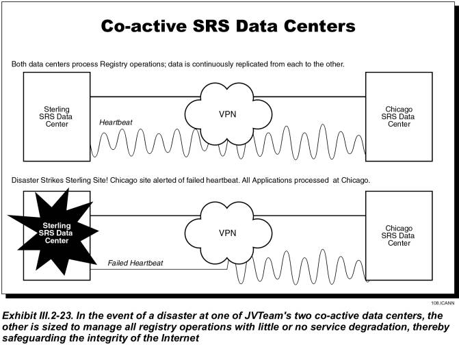
III.2.11.1�� Defining and Quantifying Quality of Service
JVTeam defines quality of service as the high-availability
aspect of the entire TLD registry
system as perceived by the registrars, registrants, and other end users. In
this context, system availability is a function of both reliability (of
hardware and software components) and performance (response time, throughput,
etc.). Other related factors include system management, diagnostics, and
maintenance; software QA; and database backup and recovery procedures.�
JVTeam has
developed the following list of service level requirements:
Service
Availability, SRS�The
amount of time in a month that registrars are able to initiate sessions with
the registry and perform standard daily functions such as; add a domain name,
transfer a domain name, etc.� JVTeam is
engineering the SRS service for 99.95% availability.
Service
Availability, Nameserver�The
amount of time in a month that internet users are able to resolve DNS queries
to the TLD nameserver network.� JVTeam
is engineering the nameserver service for 99.999% availability.
Service
Availability, Whois�The
amount of time in a month that internet users are able to initiate a Whois
query to the TLD Whois service and receive a successful response.� JVTeam is engineering the Whois service for
99.95% availability.
Update
Frequency, Zone File�The
amount of time it takes for a successful change to zone file data to be propagated
throughout the TLD nameserver network.��
JVTeam is engineering the updates to take place in near real-time and no
longer than 10 minutes.� An SLR for this
service would be crafted in the following manner; 15 minutes or less for 95% of
the updates.� �
Update
Frequency, Whois�The amount
of time it takes for a successful change to Whois data to be propagated
throughout the TLD Whois Databases.��
JVTeam is engineering the updates to take place in near real-time and no
longer than 10 minutes.� An SLR for this
service would be crafted in the following manner; 15 minutes or less for 95% of
the updates.��
Processing
Time; Add, Modify, Delete�The
time from when the registry receives an add, modify or delete action to when it
acknowledges the action.� JVTeam is
engineering for 500 milliseconds.�
Processing
Time; Query a Name�The time
from when a registry receives a query to when it returns a response.� JVTeam is engineering for 100
milliseconds.�
Processing
Time; Whois�The time from
when the registry receives a Whois query to when it returns a response.� JVTeam is engineering for 300
milliseconds.�
In addition to
these SLRs there should also be SLRs for administrative functions such as
abandonded call rates, scheduled service unavailability notification, unscheduled
service unavailability notification, etc.�
Because these
service levels are so important to ICANN and the internet community JVTeam is
willing to negotiate and report on a regular basis a list of service level
agreements (SLA) with ICANN.� We are confident
that our experience, engineering and operations expertise will deliver the
highest reasonable level of service attainable for such a complex and important
service.�
III.2.11.2�� Analyzing Quality of Service
JVTeam uses system/network-monitoring capabilities and cluster-management fault-detection services to gather systems and network performance statistics and to track device/process/interface availabilities.� The system stores this data in a local database, then generates a wide variety of pre-programmed and custom reports that enable us to:
� Track system compliance with SLAs
� Perform performance management and track system performance and resource utilization
� Perform trend analyses
� Perform capacity planning.�
We will provide
ICANN with detailed reports on component availability, circuit-utilization
levels, and CPU loads at the servers and routers. We summarize performance data
and compare it to SLAs.� We will make
performance statistics for the previous year available online; for earlier
years, from backups.
For the TLD registry service, JVTeam will also employ the statistics-generating and reporting capabilities inherent in BIND version 9.� BIND 9�s statistics-logging function reports, at selected intervals, the number of queries processed by each server, categorized by query type.� We will automatically collect and generate online reports for ICANN, detailing DNS query/response loads both on individual servers and the entire system.� By deploying application-, systems-, and network-level statistics-collection and capacity-planning tools, JVTeam can provide comprehensive reporting and trending information to ICANN.
III.2.12������ System Outage
Prevention (RFP Section D15.2.12)
The JVTeam�s co-active redundant data centers and high-availability server cluster architecture will maintain continuous operations with no disruptions in service. The benefit to ICANN is improved system availability, minimum downtime, and high confidence in the Internet registry services.
The Internet community requires outage-prevention measures specifically designed to minimize system downtime. Downtime can be categorized as either unplanned or planned:
� Unplanned downtime is caused by failures; e.g., external telecommunications failures, power failures, or internal-network or computer-equipment failures.
� Planned downtime occurs when the system is unavailable due to scheduled maintenance; e.g., software or hardware upgrades and system backups.� Planned downtime is normally minimized in two ways:
- By performing backups, maintenance, and upgrades while the system remains operational (hot)
- By reducing the time required to perform tasks that can be performed only while the system is down.�
In addition to employing the preceding measures for minimizing planned downtime, system designers may use redundancy and high-availability system architectures designed to minimize unplanned outages. Many data-management operations will also have disaster recovery agreements with a business-continuity provider who provides a disaster recovery site geographically separated from the operational data center.� The intent is to maintain continuity of operations in the event of a natural or man-made disaster.
JVTeam believes these approaches alone, although commendable, are insufficient to meet the high service levels expected by ICANN and the registrar community. For example, the registry services are so specialized and component intensive that no business-continuity provider is likely to be capable of resuming services without a lengthy outage period.� We contend that the only way to satisfy the service level requirements is through a combination of approaches, including:
� Co-active redundant data centers with two-way transaction replication
� High availability server cluster architecture
� Hot backup and recovery
� Automated disaster recovery provisions.
Procedures for Problem Detection and Resolution
To best meet data center requirements for availability, flexibility, and scalability, JVTeam has designed a high availability architecture that will combine multiple computers into a cluster. Nodes in the cluster will be loosely coupled, with each node maintaining its own processor, memory, operating system, and network connectivity. Our system/network-management and cluster management tools will automatically detect and compensate for system and network faults and notify system operators.
At five-minute intervals, the network management system will �ping� network devices with Simple Network Management Protocol (SNMP) for availability and poll them for performance statistics.� Event threshold violations or error conditions will initiate a sequence of alerting events, including visual notifications via a topology map, an entry into a trap log of event records, emails to a bulletin board, and notices to technical support staff. The goal is to detect and repair potential problems before services are disrupted.
An SNMP daemon will be configured to periodically check the status and health of vital server processes.� In the event of a critical process failure, the SNMP agent will send a trap to the network management system, initiating an alert to the technical support staff.� Our network management software will include remote monitoring and management of operations, so technical support staff can easily diagnose and troubleshoot network faults, either from the Network Operations Center or remotely. Once a problem is detected, it will be resolved using our proven problem management process. In conjunction with this problem management process, we will employ proactive performance management and trend analysis processes to do root cause analysis and discover performance and utilization trends that could lead to potential problems.
The cluster management software will organize multiple nodes (up to 16) into a high availability cluster that delivers application processing support to LAN/WAN attached clients. The cluster software, which will monitor the health of each node and quickly respond to failures to eliminate application downtime, will automatically detect and respond to failures in the following components:
� System processors
� System memory
� LAN media and adapters
� System processes
� Applications processes
� Disk drives.
Since high availability is a primary design goal, a cluster cannot have a single point of failure; accordingly, we will employ RAID mirrored disk drives and multiple LAN connections. The cluster software will monitor these hardware and software component and respond by allocating new resources when necessary to support applications processing. The process of detecting failures and restoring the applications service will be completely automated�no operator intervention will be required.
Redundancy of Data Centers and Systems
JVTeam is proposing redundant co-active data centers: one in Sterling, VA; the second, in Chicago IL. These data centers� will be interconnected by redundant, high-speed, and� secure VPN telecommunications links to provide two-way replication of all registry database transactions. A heartbeat monitor will determine the on-line status of each data center and enable the services be provided entirely from the second data center if one is lost.
Within each data center, the system will be redundantly configured so that failure of any system component will leave a configuration of surviving system components capable of executing the entire workload within 95 percent of the previous performance for at least 90 percent of users.� To achieve no-single-point-of-failure architecture, JVTeam will replicate all components and configure the system for automatic failover.
The following table describes system architecture redundancy we will employ at each SRS data center to meet 99.9+ percent service availability levels.
|
SYSTEM REDUNDANCY ELEMENTS |
||
|
Issue |
Redundancy Solution |
Benefit |
|
Single failure of a
system component |
Replicate all critical
components to eliminate single point of failures |
The system is capable of
executing the entire workload. |
|
Maintaining availability
of applications |
Stateless N+1 node
high-availability processor clusters |
In event of a processor
failure, service is not degraded. |
|
LAN Interface or Cable
Failure |
Multi-Path LAN I/O |
Automatic switchover from
one LAN switch to another to restore connectivity |
|
Disk-controller or cable
failure |
Multi-path Disk I/O |
Applications take
alternate routes |
|
Disk-storage-module
failure |
Redundant Array of Independent
Disks (RAID, levels 1, 3, and 5) |
Applications still have
access to data in the event of a single disk failure |
|
Hardware/software
upgrades and additions or changes to the configuration |
N+1 Redundancy allows hot
repair/upgrade of system components. |
Eliminate downtime due to
administrative and maintenance tasks |
|
Dynamic processor
de-allocation |
Dynamically take a
processor out of service to modify the physical and logical configuration of
the system. |
Eliminate downtime due to
maintenance tasks and component replacement |
|
Replace disks |
RAID drives and
controllers allow hot plug in of disk modules |
Eliminate downtime due to
maintenance tasks |
Hot Repair of System Components
Another advantage of system redundancy is that it will enable our maintenance staff to use hot repair replacement of system components. Keeping the system in full operation while we perform such common system-administration tasks as upgrading the hardware or software or adding to or changing components will eliminate the MTTR (Mean-Time-To-Repair) factor and will minimize downtime. Hot repair is only possible when major system components are redundant, as in the JVTeam solution.
Backup Power Supply
Each SRS and nameserver data center will be provided with UPS power to ride through brief electrical transients and outages.� For more than brief outages, each data center will have a 250 KVA motor-generator capable of running the entire data center in the event of a more lengthy electrical blackout.
Facility Security
As discussed in Registry Operator�s Proposal Section III.2.9, JVTeam will vigorously enforce physical-security measures, controlling all access to our facilities.� Throughout normal working hours, security personnel stationed at each building entrance will verify that employees are displaying proper identification badges and control access by non-employees.� Non-employees must sign in to gain entrance; the sign-in books will be stored for a period of one year.� If the purpose of a non-employee�s visit is found to be valid, he or she will be issued a temporary badge; otherwise, entrance will be denied. At all times while they are in the facility, visitors must display their badges and must be escorted by a JVTeam employee.� We will also strictly enforce the policy that employees wear their badges prominently displayed at all times while in the facility. During off-hours (6:30pm to 6:30am and all day on weekends and major holidays), individuals must use the proper-electronic key cards to gain access to the building.� We will issue electronic-key cards only to employees who need access for business purposes.
In addition to being stationed at building entrances during normal working hours, on-site security personnel will be on duty 24 hours a day and 7 days a week to monitor the images from closed-circuit television cameras placed strategically throughout the facilities.� Further, any room housing sensitive data or equipment will be equipped with a self-closing door that can be opened only by individuals who activate a palm-print reader.� Senior managers will establish the rights of employees to access individual rooms, and ensure that each reader is programmed to pass only those authorized individuals.� We will grant access rights only to individuals whose duties require them to have hands-on contact with the equipment housed in the controlled space; administrative and customer-service staffs normally do not require such access.� The palm readers will compile and maintain a record of those individuals who enter controlled rooms.�
The following table lists our physical-security mechanisms.
|
PHYSICAL-SECURITY PROVISIONS |
|
|
Mechanism |
Purpose |
|
Security guards |
Physically prevent
intruder access; verify employee badges |
|
Closed-circuit
video-surveillance cameras |
Extend capabilities of
security guards; maintain access records |
|
Intrusion-detection
systems |
Extend capabilities of
security guards to building perimeter |
|
Identity badges |
Permanent
badges for employees; easily recognizable temporary badges for visitors |
|
Sign-in registers |
Maintained as permanent
records for at least one year |
|
Electronic-key badges |
Control physical access
during off-hours; maintain access records |
|
Palm readers |
Restrict physical access
to mission-critical rooms within our facilities; maintain access records |
|
Self-closing doors |
Restrict physical access
to mission-critical rooms within our facilities |
Technical Security
Registry Operator�s Proposal Section III.2.9 also describes the technical security measures that JVTeam proposes.� We will use the underlying user-id and password security features of the XRP, supplemented by system-based Public Key Infrastructure (PKI) services to provide additional security. The following table lists the systems, protocols, and devices to prevent system hacks, break-ins, data tampering, and denial-of-service attacks.�
|
DATABASE AND OPERATING-SYSTEM SECURITY |
|
|
Technical Security-System
Element |
Features and Benefits |
|
C2 access-control
system:� User ID and password, file
level access control lists |
Ensures that the user can
access authorized functions, but no others, and can perform only authorized
operations within these functions.�
For example, the registrar of a registered domain name is authorized
to query it and then renew or cancel it or change its nameservers, but cannot
query domain names held by other registrars. |
|
Database: User ID and
password; user profiles |
�
Limits database access to pre-authorized users. �
Retains the last two passwords and disallows their usage. �
Rejects simultaneous sessions by an individual user. �
Stores user profiles. �
Limits access rights to database objects and functions to
a specified user or user group. �
Rejects unauthorized access attempts.� Automatically revokes identification codes
after a pre-established number of unsuccessful attempts. �
Provides an interface to facilitate the on-line administration
of user privileges. |
|
ECommerce-Security
Features |
|
|
SSL v3.0 protocol |
HTTPS encryption ensures
that messages between the registry and registrars can be read only by the
intended receiver. |
|
Digital signatures |
Issued by an X.509
authentication server, digital signatures ensure that the incoming data
actually has come from the purported sender; provides non-repudiation. |
|
Boundary-Security
Features |
|
|
Router |
Permits only DNS UDP/TCP
packets to enter the data center LAN, thus isolating the TLD system from most
potentially damaging messages. |
|
Firewall |
Guards the secure TLD LAN
from the non-secure Internet by permitting the passage of only packet flows
whose origins and destinations comply with pre-established rules. |
|
Intrusion Detection |
Detects intrusion at the
LAN level.� Displays an alert at the
TLD network-operations workstation and creates a log entry. |
Availability of Backup Software, Operating System, and Hardware
Registry Operator�s Proposal Section III.2.7 describes our zero-downtime/zero-impact backup process, which will use backup servers, disk array, and a DLT robotic-tape library.� The dedicated backup system will be independent of the registry server clusters that run the applications.
System Monitoring
The subsection entitled �Procedures for Problem Detection and Resolution� describes system-monitoring capabilities and procedures.� Our Network Management System and specialized element managers will monitor specific routers, LAN switches, servers cluster, firewalls, applications, and the backup servers.� In addition, the cluster-management software will monitor the status and health of processor, memory, disk, and LAN components in the high-availability cluster.
Technical Maintenance Staff
The JVTeam 3-tier customer service approach will ensure that all problems are resolved by the appropriate party in a timely manner.�
The Technical Support Group will operate out of the Help Desk Network Operations Center (NOC) within the data centers.� The group will be comprised of system administrators, network administrators, database administrators, security managers, and functional experts in the TLD registry IT systems and applications infrastructure.� Registrars access the Technical Support Group through the Tier-1 Help Desk.� This group will resolve trouble tickets and technical problems that have been escalated to them by the Help Desk Customer Service Agents. If the problem involves a hardware failure, the Technical Support Group will escalate the problem to our Tier-3 on-site maintenance technicians, third-party maintenance providers, or our hardware vendors, depending on the nature of the problem.
Server Locations
JVTeam�s registry servers will be located in the SRS data centers in Sterling, Virginia, and Chicago, Illinois.� Two zone nameserver centers will be co-located with the registry data centers; the remaining nameserver centers will be geographically dispersed with dual-homed telecommunications links and redundant high-availability servers to provide resilience and disaster recovery.
III.2.13������ System Recovery Procedures (RFP Section D15.2.13)
JVTeam is
proposing two co-active SRS data centers and a network of nameserver data
centers geographically dispersed to provide redundancy and to enable us to responsibly
recover from unplanned system outages, natural disasters, and disruptions
caused by human error or interference. ICANN and the Internet community can be
confident that we will respond to unplanned system outages quickly with little
or no loss of services.
To maintain public confidence in the Internet, ICANN requires a high level of system-recovery capabilities.� Proven industry solutions to the problems of outages and disaster recover incorporate high-availability system architectures and fast failover from the primary data center to a mirrored-backup.� High-availability solutions minimize downtime, with availability of 99.9 percent or greater. Continuously available solutions go a step further, with virtually zero downtime creating an availability of approximately 99.999 percent (five nines).
System-recovery architectures include:
� Symmetric Replication�The database replicate (on the backup or failover system) is identical to the primary database on the production system because any change made to the primary database is �replicated� in real time on the backup database. Since this is not a �two-phase commit� process, a small window of vulnerability exists, during which changes made to the primary system could be lost in transit.� Replication may increase transaction times, but switching from the primary database to the backup can be very fast and essentially transparent to end-users.
� Standby Databases�This is a special case of replication.� A standby database at a backup site originates as an identical copy of the primary database. Changes (updates, inserts, deletes) to the primary database are recorded in transaction logs that are periodically archived. Archived logs are delivered to the backup site and applied to the standby database. In a best-case scenario, the standby system is behind (in terms of data currency) the primary system by the number of changes contained on the current transaction log.
� Remote Data Mirroring�This is the classic disk-mirroring procedure, except conducted at a long distance. Depending on whether hardware or software mirroring is used, the performance impact can vary from minimal to significant. Switchover to the backup site can be quick and virtually transparent to end-users. The loss of data is zero, although a �system crash� type of database recovery is needed.
JVTeam�s system-recovery solution is based on running mission-critical SRS applications at two co-active data centers, separated by nearly 700 miles, with database-replication technology that maintains database synchronization between the two centers. To provide backup for DNS queries, we are implementing multiple nameserver data centers, also physically separated by long distances. We recognize that system management and recovery are more difficult when the system spreads over a large geographical area; however, two-way replication between the co-active SRS data centers will keep the registry master databases identical.�
III.2.13.1�� Restoring SRS Operations in the Event of a System Outage
Believing that prevention of failure is better than restoring after failure, to maximize availability and eliminate the possibility that a single-point failure could shut down operations, we implemented each of the co-active SRS data centers and four zone nameservers with:
� Redundant components with no single point of failure
� High-availability cluster architecture
� Load balancers, which are used primarily to distribute the processing load across multiple servers, defend against common denial-of-service attacks that can precipitate outages caused by processor overloads
� Fault-tolerant hardware
� Data backup/restore systems that work together to avoid unplanned outages.� (Naturally, the primary function of these systems remains quick recovery, should such an outage occur.)
The recovery mechanisms we will implement include:
� Full backup and continuous, incremental backup CD ROMs and DLT Tapes are maintained at the data center and at the secure escrow facility.� These backups enable us to recover, rebuild, and return to operation the operating system, application software, and databases.
� Processor nodes in the cluster are monitored (and controlled) by cluster-management software to facilitate recovery of software applications in the event of a processor failure.
� In the event of a database failure, fault-tolerant database software fails over to the replicated backup database, enabling applications using database services to recover operations seamlessly.
� Processors in high availability clusters have dual attach ports to network devices and RAID disk arrays, enabling them to recover from a failure in a single port or disk drive.
� Our high availability clusters are sized to run at peak load. If a processor fails, the excess capacity in the cluster handles the full processing workload while the failed node is repaired or replaced.� In essence, this is instantaneous recovery.
The remainder of this subsection describes how we would recover from a system-wide disaster; e.g., one that disables an entire data center. Subsection III.2.13.3 discusses recovery from various types of component failures.�
Each of the co-active data centers is sized to take over the entire load of the SRS operations, and each zone nameserver is dual-homed to each data center.� With this architecture, recovery in the event of a disaster is nearly instantaneous. Sessions that were dropped by the data center that suffered the disaster are simply re-started on the remaining data center within seconds. The main issues that our disaster-recovery strategy solves include:
� Instead of having a primary and a backup data center, we use two co-active data centers whose data and applications are kept synchronized by two-phase commit replication.� Because the XRP servers are configured to retry failed transactions, neither registrars nor users submitting queries will perceive any degradation in service.�
� If a data center goes off-line, the workload is transparently switched to the remaining data center.� The transaction latency is limited to the brief time needed to replicate the last transaction to the surviving data center.
� Two-way replication of transactions between the sites keeps each site�s databases in a state of currency and synchronization that is consistent with mission critical availability levels.
The use of co-active data centers with two-way replication between them provides fast, simple disaster recovery that maintains continuity of operations � even in the event of a major disaster. The resulting zero-downtime/zero-impact system not only solves system recovery problems, it also sustains confidence in the Internet.� The following are the procedures that are followed to restore operations if an SRS or nameserver data center experiences a natural or man-made disaster:
� SRS or nameserver operations are immediately failed over to the co-active data centers; registry operations proceed uninterrupted, except for those transactions that were in transit between the two centers.
� We implement the disaster recovery plan for the failed data center and place the disaster recovery team on alert.
� Within eight hours, the disaster recovery team is assembled and dispatched to the failed data center to help the local data center personnel stabilize the situation, protect the assets, and resume operations.
� The disaster recovery team assesses whether the building housing the data center can be used to recover operations.
- If so, the team contacts disaster recovery specialist firms under contract to JVTeam to secure the facility and begin recovery operations.
- If not, the team salvages equipment and software assets to the extent possible and procures an alternate data-center facility. JVTeam initiates its contingency plan to reconstruct the data center in the new location, repair and test the salvaged equipment and software, and procure the remaining required components with quick-reaction procedures.
� Once the disaster recovery team has stabilized and tested the SRS or nameserver equipment, it retrieves the system and application software CD ROMs and the database backup tapes from the secure escrow.� It then rebuilds the data center using the same recovery procedures that are used restoring components lost in a more limited failure. (Subsection III.2.13.3 describes these procedures.)
III.2.13.2�� Redundant/Diverse Systems for Providing Service in the Event of an Outage
JVTeam is proposing two co-active SRS data centers and multiple zone nameserver data centers with high availability clusters and cluster management software that enables multiple node processors, in conjunction with RAID storage arrays, to quickly recover from failures.� The server load balancer and the cluster manager software monitor the health of system processors, system memory, RAID disk arrays, LAN media and adapters, system processes, and application processes.� They detect failures and promptly respond by reallocating resources.
Dual fault-tolerant database servers are coupled to a primary and a backup database and RAID configuration to ensure data integrity and access to the database. The database system uses synchronous replication, with two-way commits to replicate every transaction to the backup database. The process of detecting failures and restoring service is completely automated and occurs within 30 seconds with no operator intervention required.�
III.2.13.3�� Process for Recovery From Various Types of Failures
The following table lists the possible types of failures and describes the process for recovery.
|
FAILURES AFFECTING THE ZONE NAME SERVER SITES |
|
|
Failure Type |
Recovery Process |
|
Nameserver cluster processor
fails |
Cluster management
software logs out the failed processor and processing continues on the
remaining nodes in the cluster. |
|
Internet or VPN link
fails |
Ongoing sessions are
dropped and restarted on the other redundant ISP or VPN-access link Ongoing sessions are
dropped and restarted on one of the other nameserver sites |
|
Edge Router, Firewall, or
Load Balancer Fails |
Ongoing sessions are
dropped and restarted on the redundant components. |
|
FAILURES AFFECTING THE DATA
CENTER APPLICATIOINS AND DATABASE SERVER |
|
|
Failure Type |
Recovery Process |
|
Applications-cluster processor
fails |
Cluster management
software logs out the failed processor and processing continues on the
remaining processors in the cluster. |
|
XRP server processor
fails |
Registrar session is
dropped from the failed server and restarted on the other XRP server |
|
Web server processor
fails |
Cluster management
software logs out the failed processor and processing continues on the
remaining processors in the cluster. |
|
Database server processor
fails |
The operating system
automatically distributes load to the remaining SMP processors |
|
Database disk drive fails |
Processing automatically
continues on the RAID with no data loss |
|
Database crashes |
The applications
processing seamlessly continues on the backup replicate database |
|
Authentication server
fails |
Processing automatically
continues on the redundant authentication server |
|
Whois-cluster processor
fails |
Cluster management
software logs out the failed processor and processing continues on the
remaining processors in the cluster |
|
A Billing server fails |
Processing automatically
continues on the redundant B&C server |
|
Internet or VPN link
fails |
Ongoing sessions are
dropped and restarted on the other redundant ISP or VPN-access link |
|
Router or firewall fails |
Ongoing sessions are
dropped and restarted on the remaining redundant router or firewall. |
In all cases of component failure, system recovery is automatic, with zero downtime and zero impact on system users.� The remainder of this subsection (III.2.13.3) provides additional information about failure recovery considerations for individual components.
Recovery From a Cluster Processor Failure
If one processor in a cluster fails, the cluster manager software logically disconnects that processor. While technicians repair or replace it, applications and user sessions continue on the remaining cluster processors. After the failed processor is off-line, the following procedures are used to recover it:
1. Testing and troubleshooting with diagnostic hardware and software to determine the root cause (e.g., hardware [CPU, memory, network adapter] or software [system or application subsystem])�
2. Repairing hardware failures and, if necessary, rebuilding system and applications software from the backup CD ROM
3. Testing the repaired processor and documenting the repairs in the trouble ticket
4. Logging the processor back into the cluster.
Database System Recovery
Our database-management system supports continuous operation, including online backup and management utilities, schema evolution, and disk space management. All routine database maintenance is performed while the database is on line.
JVTeam�s fault-tolerant database server software solution will provide distributed redundancy by implementing synchronous replication from a primary database server to a backup database server. This solution includes automatic and transparent database fail over to the replicated database without any changes to application code or the operating system.
If a database-system node experiences a hardware failure or database corruption, JVTeam technicians use the following recovery procedures:
1. Test and troubleshoot with diagnostic hardware and software to determine the root cause (e.g., hardware [CPU, memory, network adapter, RAID disk array] or software [operating system, database system, monitoring software])
2. Repair hardware failures and, if necessary, rebuild operating system and applications software from the backup CD ROM.
3. Test the repaired processor and document the repairs in the trouble ticket.
4. Restore the data files by applying (in the correct sequence) the full backup DLT tapes and the incremental backup DLT tapes maintained in the data center
5. Log the processor node back into the fault-tolerant server configuration and synchronize the database by applying the after-image journal files until the primary and replicate database are fully synchronized. The procedure is as follows:
� Recreate the database directories and supporting file structure
� Insert the full backup tape from the escrow facility and restore the base level backup.
� Insert incremental backup tapes in the correct order to ensure they are correctly applied to the base level backup.
� Using the log roll forward recovery, mount the roll forward recovery tapes and apply them to the database.
III.2.13.4�� Training of Technical Staff Who Will Perform Recovery Procedures
JVTeam technical personnel have an average of five years of data-center operations experience, encompassing the high-availability cluster technology, distributed database management systems, and LAN/WAN network management systems that are employed in the recovery process. New hires and transfers to JVTeam�s TLD registry operations will be given the following training:
� A one-week �TLD Registry Overview� course
� Vendor offered courses for certification in backup/recovery, cluster management, system management, and network management
� On-the-job training on registry operations, including high availability cluster management, system backup/recovery, database backup/recovery, and system/network management.
III.2.13.5�� Software And Operating Systems for Restoring System Operations
JVTeam will use commercially available Unix operating
systems, cluster management software, and backup/recovery software to restore
the SRS and nameserver systems to operation.�
In addition to providing synchronous replication of registry
transactions to the backup server, our database-management system will provide
data recovery services using the DLT tape backup system.� Backup/recovery hardware and software at the
SRS data center will remotely back up and restore the nameservers over the VPN.
All static applications software and operating systems are backed up to DLT tape volumes and converted to CD ROM for quick restoration in the event of operating system or application software failures. Backup copies are maintained in the data center for quick access, with additional copies in the secure escrow facility.
III.2.13.6�� Hardware Needed to Restore and Run The System
The two co-active data centers will house the commercial off-the-shelf, fault-tolerant cluster servers and dedicated backup/recovery servers that are needed to restore the system to operation.
III.2.13.7�� Backup Electrical Power Systems
Each of the two data centers is configured with a UPS battery-backup system that provides sufficient power for 30 minutes of operation.� They also have a transfer switch connected to 1000-KVA motor generators that are capable of powering the entire data center for many days without commercial power.
III.2.13.8�� Projected Time for Restoring the System
Two co-active data centers, each with high-availability clusters sized to handle the full projected registry load, provide the SRS services.
� If an individual cluster experiences a processor failure, that processor�s applications are transferred to another processor within approximately 30 seconds; however, the remaining processor nodes in the cluster continue applications processing without interruption.
� Since there are two co-active data centers with two-way database replication to maintain database synchronization, even if a natural or man-made disaster eliminates one data center, registry services continue with zero downtime and zero impact on users.� The only impact is transitional, with dropped sessions to the RP server, Whois Server, and Name Servers.� Because the protocols reinitiate a failed transaction, even these operations are fully restored in less than 30 seconds with no loss of data or transactions.
III.2.13.9�� Testing the System-Restoration Process
JVTeam will test disaster recovery plans and outage
restoration procedures annually to ensure that they can effectively restore
system operations.
III.2.13.10 Documenting System Outages
System-problem documentation includes the following:
�
The system manager and network manager systems collect
performance and utilization statistics on system processors, system memory, LAN
media and adapters, routers, switches, system processes, and applications
processes.�
�
The automated help desk database contains documentation
on trouble tickets, whether system generated or generated by the Help Desk
�
The trouble ticket database contains the documentation
of the steps taken to resolve trouble tickets
�
The data center manager collates, analyzes, and reports
monthly statistics on help desk activities, system utilization and performance,
and outages.� �
III.2.13.11 Documenting System Problems that Could Result in Outages
JVTeam�s proactive systems management processes include performance management, trend analysis, and capacity planning. These processes analyze system performance and utilization data to detect bottlenecks and resource utilization issues that could develop into outages. Monthly reports on the three processes keep the data center manager appraised of our performance against service level agreements and raise awareness of potential problems that could result in outages.
In addition, JVTeam performs root cause analysis of hardware and software failures to determine and analyze the reason for any failure. Based on our findings, we work with vendors to generate hardware service bulletins and software maintenance releases to prevent re-occurrence of these failures.
III.2.14������ Technical and Other Support (RFP Section D15.2.14)
In addition to maintaining our central Help Desk and technical-support team, JVTeam will offer Web-based self-help support via the tld.JVTeam.TLD portal. This enables registrars to access our domain-name-application process, a knowledgebase, and frequently asked questions.
ICANN requires technical support for the rollout of any new TLD registry services, as well as for continuous registry operations. This technical support must satisfy several criteria:
� It must support all ICANN-accredited registrars
� To support the world�s different time zones, access must be available worldwide, 7x24x365
� It must accommodate the anticipated �Land Rush� when the new TLD names are opened for registration.
The ICANN registry model provides a clear, concise and efficient deliberation of customer support responsibilities. Registrars provide support to registrants and registries provide support for registrars. This allows the registry to focus its support on the highly technical and administratively complex issues that arise between the registry and the registrar.
III.2.14.1�� Technical Help Systems
Registrars have a great deal of internal technical capability because of their need to support an IT infrastructure for their marketing and sales efforts and for their customer-support and billing-and-collection services.� JVTeam will enhance these registrar capabilities by providing the registrars with the following types of technical support.� All will be available on a 24 x 7 x 365 basis. The JVTeam will make their best effort to provide service in multiple languages.� The services are:
� Web-based self-help services, including:
- Knowledge bases
- Frequently asked questions
- White papers
- Downloads of XRP client software
- Support for email messaging
� Telephone support from our central Help Desk
� Fee-based consulting services.�
Web Portal� (tld.jvteam.tld)
JVTeam will implement a secure Web-based multimedia portal to help support registrar operations. To obtain access to our Web-based services, a registrar must register his registrants with us, and must have implemented our security features, including SSL encryption, log in with user ID and password, and digital certificates for authentication.
The home page of the web portal will include a notice to registrars of planned outages for database maintenance or installation of software upgrades.� This notification will be posted 30 days prior to the event in addition to active notification including phone calls and email.� We will also record outage notifications in the help desk database to facilitate compliance with the service-level agreement. Finally, seven days and again two days prior to the scheduled event, we will use both an email and a Web-based notification to remind registrars of the outage.�����
Non-affiliated registrars and the general Internet community may obtain generic information from JVTeam�s public Web site, which will describe our TLD service offerings and list ICANN-certified registrars providing domain-name services.
Central Help Desk
In addition to implementing the Web site, we will provide telephone support to our registrars through our central Help Desk. Access to the help desk telephone support is through an automatic call distributor that routes each call to the next available customer support specialist.� We will authenticate callers by using caller ID and by requesting a pre-established pass phrase that is different for each registrar.� Requests for assistance may also come to the Help Desk via email, either directly or via the secure Web site.�
The Help Desk�s three tiers of support are:
Tier-1 Support�Telephone support to registrars who normally are calling for help with customer domain-name problems and such other issues such as XRP implementation or billing and collection. Problems that can�t be resolved at Tier 1 are escalated to Tier 2.
Tier-2 Support�Support provided by members of the technical support team, who are functional experts in all aspects of domain-name registration.� In addition to resolving escalated Tier 1 problems with XRP implementation and billing and collection, Tier 2 staff provides technical support in system tuning and workload processing.�
Tier-3 Support�Complex problem resolution provided by on-site maintenance technicians, third party systems and software experts, and vendors, depending on the nature of the problem.
In turn, the Help Desk uses an automated software package to collect call statistics and record service requests and trouble tickets in a help desk database.� The help desk database documents the status of requests and tickets, and notifies the Help Desk when an SLA threshold is close to being breached.� Each customer-support and technical support specialist uses our problem management process to respond trouble tickets with a troubleshooting, diagnosis, and resolution procedure and a root-cause analysis.
Escalation Policy
Our escalation policy defines procedures and timelines for elevating problems either to functional experts or to management for resolution if they not resolved within the escalation-policy time limits. The following table is an overview of our escalation policy.
|
Level |
Description |
Escalation
Policy |
Notification |
|
I |
Catastrophic outage affecting
overall registry operations |
Data-center manager escalates
to JVTeam management and Disaster-Recovery Team if not resolved in 15 minutes
|
Web portal and e-mail notifications
to all Registrars within 15 minutes; updates every 30 minutes |
|
II |
Systems outage affecting
one or two registrar sessions but not the entire system |
Systems engineer
escalates to data-center manager if not resolved in one hour |
Web-portal notification
to all registrars; hourly updates |
|
III |
Technical questions |
Help Desk
customer-support specialist escalates to the systems engineer if not resolved
in two hours |
Hourly updates to registrar
via e-mail |
|
IV |
Basic questions |
Help Desk
customer-support specialist escalates to the systems engineer if not resolved
within four hours |
Hourly updates to registrar
via e-mail |
III.2.14.2�� Staffing
Initially, JVTeam will staff its Help Desk with a complement of customer service specialists, enabling us to operate three shifts providing 24 x 7 x 365 coverage. We will add staff as necessary to respond to incoming requests within the service-level agreement.� Customer-service specialists will obtain assistance from JVTeam�s technical staff for any problems that cannot be resolved in one phone call.
III.2.14.3�� Test� and Evaluation Facility
JVTeam will establish an operational test-and-evaluation facility that will be available 24 x 7 x 365 for registrars to test their client XRP system. Our technical-support team, which consists of functional experts in the processes and technologies for domain-name registration, will support the registrars� testing.
Once each new registrar is satisfied that its system is compatible with the registry system, it will schedule a formal acceptance test that will be monitored by our system engineer. After a registrar has passed the acceptance test, we will issue its user id, passwords, and digital certificates, and the registrar can begin operations.
III.2.14.4�� Customer Satisfaction Survey
To determine registrars� satisfaction with registry services, JVTeam will implement a Web-based customer-satisfaction survey that will consist of a set of survey questions with responses ranging from one to five on the Likert Scale.� We will tabulate the results and publish them on the Web site.
To further verify the quality of our customer services, JVTeam will commission a biannual customer-satisfaction survey by an independent third party.