Technical Plan
(Including Transition Plan)
![]()
![]() Table
of Contents > Section III
Table
of Contents > Section III
|
Technical Plan |
|
|
||
|
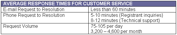
Section III — Technical Plan (Including Transition Plan) PIR’s back-end registry services provider, Afilias, will provide a proven, world-class suite of services to serve .ORG registrars and registrants. This will help PIR make the .ORG registry the first to operate in the public interest, and allow PIR to deliver the highest level of customer satisfaction in the domain name industry. Leveraging expertise gained from operating the .INFO TLD, Afilias’
services will speed resolution times, increase reliability, enhance security,
protect information, and provide stability to .ORG. These services include
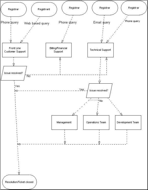
core functions such as conformance to registry-registrar models and protocols, Afilias has an experienced technology management team leading an expert staff of technical support, customer service, and product management specialists who assist registrars and registrants every hour of the year. This disciplined team has created well-defined processes that allow it to avoid emergencies and quickly address issues as they arise. Afilias pioneered the use of EPP, and is the registry that possesses
the most experience with it. Afilias already supports more than 800,000
.INFO domains, and has executed over 20,000 transfers to date. Afilias’
systems and technology base are standards-compliant, flexible, fault-tolerant,
and Afilias has developed a comprehensive plan to transparently migrate the
.ORG domain with no interruption to DNS or WHOIS services, and with minimal
impact on registrars. Afilias has directly relevant experience in this
area, since it helped design and test the new registry system for the Afilias’ combination of proven technology, strong leadership, customer advocacy, and operational excellence provides a solid foundation for PIR’s stewardship of the .ORG domain. The third section of the .org Proposal is a description of your technical plan. This section must include a comprehensive, professional-quality technical plan that provides a full description of the proposed technical solution for transitioning and operating all aspects of the Registry Function. The topics listed below are representative of the type of subjects that will be covered in the technical plan section of the .org Proposal. C17. Technical Plan for Performing the Registry Function Technical plan for performing the Registry Function. This should present a comprehensive technical plan for performing the Registry Function. In addition to providing basic information concerning the proposed technical solution (with appropriate diagrams), this section offers the applicant an opportunity to demonstrate that it has carefully analyzed the technical requirements for performing the Registry Function. Factors that should be addressed in the technical plan include:
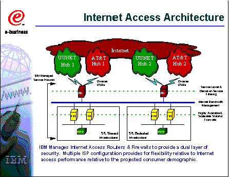
Under the terms of PIR's contract with Afilias, Afilias will provide back-end registry operations for the .ORG TLD. Afilias has extensive experience in the operations of a top-level domain. Afilias owns Liberty Registry Management Services Company (Liberty RMS), located in Toronto, Canada. Liberty's speciality is the technical development and operation of registries, including the .INFO TLD and the .VC ccTLD. Afilias has entered into several long-term contracts with industry-leading firms to provide data center, globally distributed DNS, and data escrow services. The registry's Tech Support and Operations Monitoring group are located in Toronto, Canada. All registry systems will be located within IBM secure data centers, which conform to these minimum security standards:
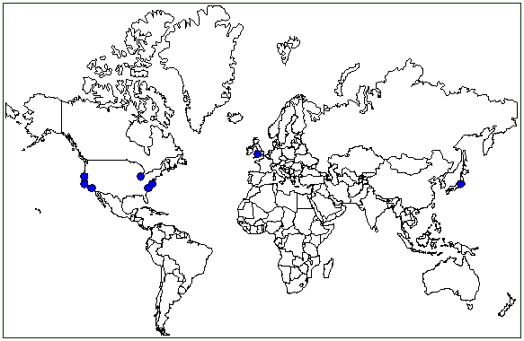
IBM Hosting Delivery Centers are located worldwide and share modeled service offerings. Afilias currently utilizes IBM facilities in St. Louis, MO and West Orange, NJ. Due to the nature of Afilias' agreement with IBM, the .ORG registry has the option of utilizing IBM data centers in geographically separated locations worldwide. These worldwide locations include:
b. Primary Site: IBM V3 facility (Fully Managed Data Centers) Primary facilities are fully hosted solutions in V3 telco-grade, high security buildings. Only IBM staff has access to the physical environment, servers, network devices, and so on.
Multiple air conditioning units are configured in a fully redundant array. Multiple UPS power units with battery backup provide clean and reliable electrical power. Multiple diesel generators, also in a fully redundant array, are available during extended power outages.
Server racks, cases, network cables and components are systematically labeled with color coded identifiers; minimizing the possibility of any human error during plant services work, and accelerating trouble-shooting capabilities in the event of equipment failure.
Security guards are on duty 24/7, and enforce a sign-in process where IBM staff entering the facility must be on the approved list and be accompanied by a minimum of one other IBM staff member. The entire facility is monitored by video surveillance.
c. Secondary and All Other Fail-over Production Sites: IBM V5 Facilities (Managed and Self-Managed Data Centers) All fail-over facilities are co-located in telco-grade, high-security buildings. Security guards are on duty 24/7, and enforce a sign-in process where anyone entering the facility must be on the approved list. Visitors must show legal photo ID to be granted access to each facility. Once inside the facility, visitors must use a card key and palm scanner to gain access to the data center. The registry systems are locked within cages in the data center and must be unlocked by security. The entire facility is monitored by video surveillance. Multiple air conditioning units are configured in a fully redundant array. Multiple UPS power units with battery backup provide clean and reliable electrical power. Multiple diesel generators, also in a fully redundant array, are available for extended power outages.
|
|
|
|
The specifications of the individual servers are described below. As technology improves and new hardware and systems technology becomes available, the registry intends to upgrade its servers and systems to well-tested systems at periodic intervals. i. Primary Site Shared Application Servers: The following application servers are distributed on two physical Enterprise Sun Servers for N+1 Redundancy.
Two (2) Database Servers
Two (2) Dedicated Application Layer Firewalls (VPN)
Two (2) Dedicated Database Firewalls (VPN)
Two (2) Load Balancer Switches
Two (2) Rate Limiter Switches
Two (2) Server Access Switches
Dedicated TSM (Backup System)
ii. Secondary Site: Shared Application Servers:
One (1) Database Server
Two (2) Support Services Servers (i.e. Reports)
Two (2) Enhanced Registry Services Servers
Two (2) O T &E Servers
Two (2) Server Access Switches
Two (2) Dedicated Application Layer Firewalls (VPN)
Two (2) Dedicated Rate-limiters and Database Layer Firewalls
Dedicated TSM (Backup System)
Figure 24
Figure 25
Clear separation between server and application
environments
High security levels detect and help prevent
intrusion 7x24 NOC runs best-of-breed monitoring
systems Global monitoring, customer care and escalation
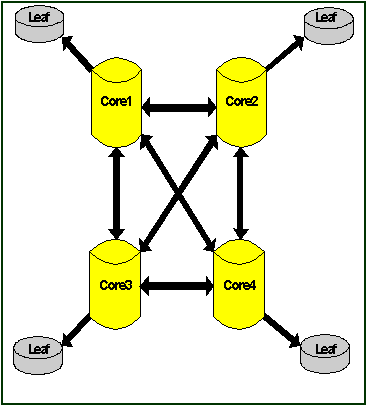
systems System redundancies exist at the hardware, database, and application layer. These are explained below. i. Hardware Layer Redundancy
ii. Database Layer Redundancy The registry operates several database servers to provide redundancy. The primary registry facility houses two database servers, one being the main database (Database A) and the other being the secondary database (Database B). Any transactions committed to the primary database are automatically replicated to the secondary database. The WHOIS service will normally operate off the secondary database server, to allow optimal use of the primary server for handling registration events. In addition, the standby registry facility will house one database server, which will be constantly synchronized with the primary registry. In the event that the primary registry's main database (A) fails, the registry application will be manually switched over to the secondary database (B); following the verification of registry data by the on-call DBA. The centralized WHOIS application will continue to use the secondary database as usual. When the main database is restored, any transactions committed to the secondary database will be replicated to the primary database. If the secondary database (B) fails, the centralized WHOIS server will automatically switch over to use the primary database (A). In the event that the primary database fails, and the registry application and the WHOIS server are both using the same database (secondary), some degradation in service is expected. If the primary and secondary database at the Primary data center fail, the registry will switch over to the standby registry facility as described in "Disaster Recovery.” iii. Application Layer Redundancy
f. Systems Capacity and Scalability i. Application Layer The registry applications are designed to have stateless operation with load balancers (See “Hardware Architecture”). This permits dynamic scaling at the application layer for all registry functions. The registry applications are expected to exercise 5-6% sustained load on the currently slated application servers, with bursted loads of up to 12-13%. The registry application server will be operated with a minimum bursted capacity of 50% over sustained loads. In the event of unexpected load increase, this available overhead should permit the registry operator to promote additional application servers into production without expected degradation of service. ii. Database Layer Database servers in use will have the capacity to dynamically add additional processors and memory. As primary services will be balanced across the two main database load averages on currently slated database servers are expected to operate at a sustained 12-15% of capacity, with bursted loads of 20-25%. The database servers will be operated with a minimum bursted capacity of 50% over sustained loads. In the event of unexpected load increase, this available overhead should permit the registry operator to add additional memory and CPU to continue to scale load appropriately. In addition, the registry operator will continually monitor new advances in database clustering technologies, with the intent of incorporating such a solution when proven reliable and secure. The registry consists of two geographically separate physical facilities—the primary and the standby (secondary). These are described above in "Hardware Architecture.” In the event that the primary facility fails, the systems will switch over to use the standby facility. This is described in more detail below. i. System Impact If the registry is operating from the secondary facility, and the primary facility is restored, any transactions that have occurred and have been recorded on the secondary facility database will be replicated to the primary facility databases (Database A & B). While the registry is operating from the standby facility, some degradation in service is expected since there will be reduced hardware and single instances of both registry application and WHOIS service accessing a single Database (as opposed to accessing separate databases as they do in the primary facility). ii. Registrar Impact Any fail-over of the system between the primary and standby registry facility will coordinated with the registrar. The registrar will be provided with the logic to query the status of the registry, and be able to switch over to the operating facility (either primary or standby) as necessary. If the registrar's application has switched over to the standby facility, once the primary registry is restored, the registrar application will be able to switch back to using the primary registry. While the registry is operating from the standby facility, some degradation in service is expected since there will be reduced hardware and single instances of both registry application and WHOIS service accessing a single database (as opposed to accessing separate databases as they do in the primary facility). The registry conducts routine backup procedures. These are performed in such a way as not to adversely impact scheduled operations. A detailed description of backup and escrow procedures is provided in C17.7. Normal backups allow retention of:
The OT&E environment provides a test bed for registrars to test their client applications against a simulated registry environment before going online. The registry also uses the OT&E environment to verify client applications for potential registrars. During client development, registrars can expect the OT&E system to operate as the production environment. The OT&E environment is hosted on multi-processor UNIX servers and represents a scaled down version of the live system. Registrar reports shall be available for download via a Reports Administrative Interface. Each registrar will be provided secure, password-protected access, to the Reports Administrative Interface. A given registrar will only have access to its own reports. Daily registrar reports are maintained for each registrar for seven days. Daily reports older than seven days will be removed. Weekly registrar reports are maintained for each registrar for four weeks. Weekly reports older than four weeks will be removed. An archive retrieval system will be available to request older registrar reports from a cold storage system and will be part of the enhanced registry services. k. Registrar-Registry Synchronization There are two methods available for the registrar to synchronize data with the authoritative-source registry. Bulk synchronization: A registrar will contact registry support and request a data file containing all domains registered by that registrar, within a certain time interval. The data file will be generated by registry support and made available for download using a secure web server. The data file will be a comma delimited file that contains all domains the registrar has registered in the time period requested—including all associated host (nameserver) and contact information. Single object synchronization via EPP: The registrar can, at any time, use the EPP <info> command to obtain definitive data from the registry, for a known object: including domains, hosts (nameservers) and contacts. There is no need to contact registry support for this synchronization method. l. Hardware and Architecture Disclaimer The registry operator may adjust the both the equipment list and systems architecture in respect of the continuing advancement of both registry functions and hardware/operating systems in the market place. Any changes therein will not adversely affect the sustained performance, reliability, stability, or security of the registry.
The new .ORG registry will conform to the latest version of the Extensible Provisioning Protocol (EPP). At the time of submission of this bid, the most current version is EPP-06, a draft version that has been submitted for ratification into an Internet standard. Since a large part of ISOC’s membership is drawn from the Internet Engineering Task Force (IETF), the registry will implement technology solutions promptly upon adoption as an Internet standard.
1. EPP Registry-Registrar Model (Extensible Provisioning Protocol) Overview: The .ORG registry implementation will feature a "thick"
model as typified by the rich object store managed by the centralized
registry. This object store can be managed by accredited registrars via the SRS interface that will be using the interface protocol specified by the January 24, 2002 IETF Hollenbeck Extensible Provisioning Protocol (EPP) drafts. As these drafts progress through the standards process, the registry will, where appropriate, ensure that the most current version of the standard is supported as outlined in the "Protocol Development/Change Management" section below.
It is the intent of this portion of the document to provide registrar operations development support staff with an overview of the EPP protocol by which they can guide their integration efforts.
The EPP specification is broken up into an extensible object design with each of the primary objects given an individual but consistent interface that meet the base EPP framework as described below:
a. Registry Protocol Highlights (EPP) i. Generic RRP Requirements (draft-ietf-provreg-grrp-reqs-06) URL: http://search.ietf.org/internet-drafts/draft-ietf-provreg-grrp-reqs-06.txt
This document describes high-level functional and interface requirements for a client-server protocol for the registration and management of Internet domain names in shared registries. Specific technical requirements detailed for protocol design are not presented here. Instead, this document focuses on the basic functions and interfaces required of a protocol to support multiple registry and registrar operational models.
ii. Base EPP Framework (draft-ietf-provreg-epp-06) URL: http://search.ietf.org/internet-drafts/draft-ietf-provreg-epp-06.txt
This document describes the foundation upon which all of the specific objects (Domains, Hosts, Contacts) must adhere to in order to maintain a consistent interface. A standard registry specific extensible object management framework is also described in this document to handle any extra information need to satisfy policy or other agreements the registry may be required to sustain.
iii. EPP TCP Server (draft-ietf-provreg-epp-tcp-04) URL: http://search.ietf.org/internet-drafts/draft-ietf-provreg-epp-tcp-04.txt
This document dictates the TCP connection strategies to use and is almost identical to the existing NSI RRP implementation. Therefore, the EPP Server implementation structure will mirror the existing RRP Server design using TCP/IP and SSL to secure transport.
iv. Domains (draft-ietf-provreg-epp-domain-04) URL: http://search.ietf.org/internet-drafts/draft-ietf-provreg-epp-domain-04.txt
This document describes an Extensible Provisioning Protocol (EPP) mapping for the provisioning and management of Internet domain names stored in a shared central repository. Specified in XML, the mapping defines EPP command syntax and semantics as applied to domain names.
v. Hosts (draft-ietf-provreg-epp-host-04) URL: http://search.ietf.org/internet-drafts/draft-ietf-provreg-epp-host-04.txt
This document describes an Extensible Provisioning Protocol (EPP) mapping for the provisioning and management of Internet host names stored in a shared central repository. Specified in XML, the mapping defines EPP command syntax and semantics as applied to host names.
vi. Contacts (draft-ietf-provreg-epp-contact-04) URL: http://search.ietf.org/internet-drafts/draft-ietf-provreg-epp-contact-04.txt
This document describes an Extensible Provisioning Protocol (EPP) mapping for the provisioning and management of identifiers representing individuals or organizations (known as "contacts") stored in a shared central repository. Specified in XML, the mapping defines EPP command syntax and semantics as applied to contacts.
vii. Supported Command Set The registry will provide the following command sets to support the Registry Service.
The command sets are described in more detail below.
viii. Greeting
An EPP server shall respond to a successful connection by returning a greeting to the client. The greeting response includes information such as:
ix. Session Management Commands
EPP provides two commands for session management: <login> to establish a session with a server, and <logout> to end a session with a server.
Login
The EPP <login> command is used to establish a session with an EPP server in response to a greeting issued by the server. A <login> command MUST be sent to a server before any other EPP command.
Logout
The EPP <logout> command is used to end a session with an EPP server.
x. Object Query Commands
EPP provides three commands to retrieve object information: <info> to retrieve detailed information associated with a known object, <check> to determine if an object is known to the server, and <transfer> to retrieve known object transfer status information.
These are described below.
Info
The EPP <info> command is used to retrieve information associated with a known object. The elements needed to identify an object and the type of information associated with an object are both object-specific, so the child elements of the <info> command are specified using the EPP extension framework.
Check
The EPP <check> command is used to determine if an object is known to the server. The elements needed to identify an object are object-specific, so the child elements of the <check> command are specified using the EPP extension framework.
Transfer (Query)
The EPP <transfer> command provides a query operation that allows a client to determine real-time status of pending and completed transfer requests. The elements needed to identify an object that is the subject of a transfer request are object-specific, so the child elements of the <transfer> query command are specified using the EPP extension framework.
xi. Object Transform Commands
EPP provides five commands to transform objects: <create> to create an instance of an object with a server, <delete> to remove an instance of an object from a server, <renew> to extend the validity period of an object, <update> to change information associated with an object, and <transfer> to manage changes in client sponsorship of a known object.
These are described below.
Create
The EPP <create> command is used to create an instance of an object. An object may be created for an indefinite period of time, or an object may be created for a specific validity period. The EPP mapping for an object MUST describe the status of an object with respect to time, to include expected client and server behavior if a validity period is used.
Delete
The EPP <delete> command is used to remove an instance of a known object. The elements needed to identify an object are object-specific, so the child elements of the <delete> command are specified using the EPP extension framework.
Renew
The EPP <renew> command is used to extend the validity period of an object. The elements needed to identify and extend the validity period of an object are object-specific, so the child elements of the <renew> command are specified using the EPP extension framework.
Transfer
The EPP <transfer> command is used to manage changes in client sponsorship of a known object. Clients may initiate a transfer request, cancel a transfer request, approve a transfer request, and reject a transfer request.
Update
The EPP <update> command is used to change information associated with a known object. The elements needed to identify and modify an object are object-specific, so the child elements of the <update> command are specified using the EPP extension framework.
b. Protocol Development/Change Management The IETF Provisioning Registry Protocol "provreg" working group [PROVREG] has been chartered to develop a specification for the requirements and limitations for a protocol that enables a registrar to access multiple registries. The working group will also develop a protocol that satisfies those requirements. The protocol will permit interaction between a registrar's own application and registry applications. The EPP has been proposed as a candidate for this purpose.
The initial specification will allow multiple registrars to register and maintain domain names within multiple TLDs. The specification should be flexible enough to support the different operational models of registries. The specification should allow extension to support other registration data, such as address allocation and contact information.
The working group will use as input the "Generic Registry-Registrar Protocol Requirements" (draft-hollenbeck-grrp-reqs-nn) and the Extensible Provisioning Protocol presentation, documented in (draft-hollenbeck-epp-nn).
ISOC expects the activities in the working group to have significant impacts on both registry and registrar systems. As such, PIR will take the following steps to ensure that it will be able to migrate to a protocol that has been accepted as an IETF standard.
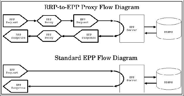
2. RRP Implementation: RRP to EPP Translation (RRP-Proxy) Overview RFC2832
Support for the current RRP protocol interface into the .ORG registry will be achieved via an RRP-to-EPP proxy. This service would provide all RRP services that are currently stated in RFC2832. A true RRP server would not exist, instead RRP key-value pairs would be translated into EPP-XML using the extension framework where needed to transmit RRP specific items to the actual EPP "thick" registry service. The RRP-to-EPP proxy would act as a temporary migration interface and would be phased out in favor of direct EPP connectivity some time in the future. This approach would minimize the impact of the new .ORG "thick" registry to all existing Registrars.
3. Helpful How-to for EPP
Registrars Appendix B provides an example of the epp-howto document that describes how to transition from RRP to EPP with the use of the epp-rtk. A copy of this document is also available within the epp-rtk project at http://epp-rtk.sf.net/epp-howto.html
Documents like this one as well as others will be made available to registrars to aid in the smooth transition from RRP to EPP. In addition, the registry operator will provide other migration services on request from registrars, to ensure that the RRP to EPP transition is relatively seamless.
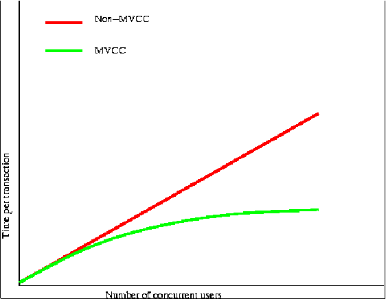
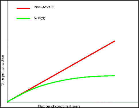
Overview: A Solid Foundation The .ORG registry will use only advanced, high-availability, enterprise-class RDBMS that compares favorably with the competition in benchmarks. The RDBMS to be used for the .ORG registry will be an extremely efficient system. The RDBMS system offers ANSI SQL99 compliance, full A.C.I.D. Transaction compliance, seriliazable and read-committed isolation, online backup, an advanced extensible data type system with a broad array of built-in types, BLOBs, a flexible and extensible function system, and standard JOIN and VIEW syntax. User-defined stored procedures may be programmed using the many built-in languages (incuding Perl, C, and Python), and an unusually flexible set of interfaces to external programming languages. It includes a flexible rules and triggers system that allows query rewrite inside transactions, and optional built-in SSL support for enhanced security. A user-driven permissions model ensures security in the database. Based on its experience, and based on the fact that the .ORG registry will be run on industry-winning solutions, we believe that the .ORG registry will rest on a solid foundation. The registry database system has been carefully designed, backed by a high-concurrency, always-available database technology. The system is very powerful, able to handle thousands of transactions per second with hundreds of concurrent registrar users. The registry database uses a relational database management system ("RDBMS") that supports the SQL99 standard. Afilias has selected its RDBMS for speed, stability, scalability, and security. The system meets all these needs. The registry's RDBMS is fast-it can handle thousands of transactions per second with hundreds of concurrent users. This speed is partly due to the efficiency and small memory footprint of the RDBMS. A small, efficient program will run faster, and return results more quickly, than a larger program. The most important barrier to speed in a registry application is concurrency: an unpredictable number of requests for the same object may arrive at the same time. One of the biggest speed advantages enjoyed by Afilias' RDBMS is the advanced multi-version concurrency control ("MVCC") it implements. MVCC solves the challenge of concurrency by responding to every query with the data appropriate to when the query arrived in the system. The result is accurate and fast, responses for every user. Multi-version concurrency control (MVCC) ensures that every user sees a view of the database proper to the transaction. Traditional locking makes for slow query times when under high load. MVCC prevents that problem, meaning that queries are just as fast for 1,000 users as they are for 100 or ten users.
MVCC means that readers never wait for writers, and writers never wait for readers. Only in the event that two clients try to update the very same row of data will access be blocked for one. Afilias uses high-powered, enterprise-class servers host the database. High-speed interfaces are used for all disk subsystems, to ensure that input/output limits do not cause performance difficulties. Multi-processor servers ensure that the RDBMS never lacks processing power. The systems have large amounts of system memory to ensure that datasets can reside in memory, rather than on disk. Hardware is regularly tuned to maximize performance without any degradation in stability and security. An extensive series of benchmarks have been run by experts in configuring the RDBMS, thereby ensuring that the configuration of the database is fast, stable, and secure. PIR's software under-girds the .INFO registry. The .INFO service-level agreements demand extremely high levels of system availability; our RDBMS technology delivers on those demands. The RDBMS is an extremely stable and reliable system. The database and its structure have been designed in such a way that the RDBMS does not stop working, even under very heavy loads (see Figure 32 above). The hardware and systems on which the RDBMS operates will be extended for use in running .ORG. These are hardened, burnt-in systems with stable configurations. The database servers will be capable of "hot plugging" all critical components, so that the failure of any piece of hardware would not halt data processing. ECC memory installed in the database servers ensure that random memory errors do not compromise data or cripple the system. Data will be stored on external, battery-backed RAID arrays, connected by multiple redundant interfaces. Multiple database servers are in used. The databases will be replicas of one another; in the unlikely event of an outage on one server, another will always be available to take its place. Please see sections C17.10 ("Peak Capacities") and C17.13 ("System Reliability") for more details. The RDBMS technology intended for use for the .ORG registry will have no internal limit in the size of the database it can support. It can easily scale to thousands of concurrent connections, executing thousands of concurrent queries, and do so efficiently. Afilias' systems, software, and staff currently support more than 10 million tuples without any noticeable effect on performance. Leveraging its experience in running the .INFO registry, Afilias will also employ similar enterprise-class, scalable hardware for the .ORG registry. Additional disk space, memory, and CPUs may be added as the .ORG registry grows and expands beyond its initial configurations. Since Afilias has significant knowledge and experience building highly scalable and available database systems, we expect to provide very reliable database performance. Growth in the database may result in the need for additional storage, additional processing power, and additional memory. The selected servers will be configured so that additional storage, memory, and processing power can be added without interrupting processing. Sample limits are indicated below for a Sun Enterprise 4500 server attached to a Sun StorEdge A5200 RAID array; different configurations will be subject to other limits: Additional storage may be added, to a maximum of 2 terabytes. No downtime is needed to increase the storage of the system. The system is efficient at storage: a thick registry of one million names needs about 10 gigabytes of storage, including all ancillary, support, and log tables. Each server will accept up to 28 gigabytes of memory, which is more than sufficient to support all the processing power of the system. The memory is used immediately by the system. Each server can accept up to 14 central processors. CPUs may be added to the system without interrupting processing. Database servers are typically configured to accommodate a 200% growth increase in the physical size of the database. Servers will be initially configured to allow for a four-times the average estimated transactions per minute currently experienced by the .ORG system. (The current load is estimated from the average traffic reported by VeriSign, Inc., for the period of March 2001 through March 2002. The estimate is based on the reports available at http://www.gtldregistries.ORG/reports/2002/apr/index.html/) A full discussion of system security is included in section C17.9. The RDBMS contributes to the security model by enforcing strong authentication, by its location in the system configuration, and by offering unparalleled long-term maintainability. The RDBMS provides a secure data store for the objects used for client authentication. A secondary authentication method, using certificates, provides a second, independent authentication method. This two-way, independent authentication prevents malicious users from accessing the system, and ensures integrity of the database. The RDBMS is located inside a private, unrouteable network, and will not allow connections except under specific conditions from inside that network. An attacker would have to break through several security layers, and then bypass the local authentication methods, in order to compromise the database directly. The RDBMS system selected for use in the .ORG registry will have the characteristic of long-term maintainability. Afilias' staff has expertise in creating long-term, sustainable vendor relationships, particularly of critical pieces such as the RDBMS. Except for database administration, all activity in the database will be performed by the SRS server, using EPP commands that the EPP server will translate to SQL queries. Section C17.2 ("Registry-registrar Model and Protocol") contains a full description of each EPP command. The system will support the full set of EPP object manipulation commands. The core database system itself will receive only standard SQL commands. This minimizes the risk of attack on the database via stored-procedure exploits, because the database will simply reject such attempted exploits. This approach performs the logical functions of data verification, interpretation, and processing in different areas of code. The result is a simpler, more secure system, which is less vulnerable to malicious or erroneous submission of data. If an object changes status, or is otherwise altered, there are three ways that registrars are notified:
Some billing events can also generate an e-mail, to warn registrars of impending limits. See section C17.6 ("Billing and Collection Systems") for more detail about e-mail notices related to billing. Various grace periods can be implemented in the system, to allow for flexible policies regarding mistaken registrations, unwanted renewals, and so on. Grace period policies are configurable. Usually, grace period policies apply only to those objects that accrue a charge when being manipulated. Further details of charge accrual are found in section C17.6 ("Billing and Collection Systems"). Some example grace policies are:
Grace period policies that take effect on direct action by a registrar are handled as part of the billing component of the EPP server. For example, a registrar must actually delete the newly created domain in the first example, above; the grace period policy will be checked by the EPP server at the time of the transaction. Some grace period events need to be scheduled, such as the "auto-renew" grace period policy (example three above). An independent module, working only within the private network, will implement such grace policies. The .ORG RDBMS will utilize functionality built into it to generate reports for the .INFO registry. As a result, a wide variety of native interfaces to its SQL engine allow reports to be generated for virtually any data in the system, and output presented in a variety of formats. Standard reports will be generated as delimited ASCII, in order to provide the maximum portability to registrars' own reporting and reconciliation platforms. The reporting system's design uses a triple-path logging mechanism, to allow for a wide variety of detailed reports to be generated efficiently, and to ensure that periodic audits of the software may be performed. Transactions are traceable through the system, both as billed events and as EPP transactions. Data is collected in such a way that trends can be identified and presented quickly and easily.
Overview The .ORG registry will benefit from Afilias' near-real-time zone file data generation and distribution system, resulting in up-to-date responses from .ORG nameservers distributed worldwide. DNS queries will be serviced entirely through one of the world's leading DNS providers, UltraDNS. UltraDNS hosts the DNS information in its own proprietary database while maintaining full compliance with international standards for providing DNS information to the Internet community. UltraDNS provides its services in such a manner as to provide DNS that is both highly available and high-performance. A more detailed description of UltraDNS's facilities and methods is included in Section C17.5 ("Zone File Distribution and Publication"). For the first time in the history of the .ORG TLD, the .ORG domain's availability will be subject to an SLA of the highest standard - a 100% network uptime commitment. Afilias will collect changes to .ORG domain information from registrars and perform frequent regular updates to the nameserver constellation in order to maintain the relevancy of the DNS information store as well as to retrieve the authoritative TLD zone file for distribution amongst the subscribing registrars. Domain Names Services provided by the registry consists of substantially three portions.
The focus of this section (C17.4) is zone generation while the supplementary topics, zone publication, and distribution are treated in more detail in the section C17.5. PIR will also make the TLD zone file available to registrars who wish to subscribe. The process for making this TLD zone file available is also detailed in this section. When registrars wish to adjust, add, or remove zone information on behalf of their registrants, they will do so using the Registrar Tool Kit (RTK) that will be provided to registrars for their use. These changes will be collected in the zone database and applied to the domain name servers over a regular and frequent interval. As the user, registrars will be required to authenticate themselves with the .ORG registry before changes will be accepted into the database for publication. The following criteria will identify a registrar at the application layer:
Registrars will only be permitted to alter domain information that they have been designated by the registrant to alter. Transfer of domains from registrar to registrar will be permitted and supported. Zone generation involves the creation of DNS zone information using the registry database as the authoritative source of domain names and their associated hosts (name servers). Updates to the zone information will be generated automatically at least every five minutes and published to the name servers. These updates will reflect any modifications, additions or deletions to the registry, that have been made by the registrars during that time period. Only changes that have been committed to the database will be reflected in the zone information update. Incomplete units of work will be ignored. The master zone file will include the following resource records:
DNS information is stored within UltraDNS' nameserver infrastructure
in a distributed relational database (as opposed to a legacy flat-file
format). This feature makes the UltraDNS data storage model more flexible
and secure than traditional implementations. Manipulation of DNS information
is achieved through equally advanced and secure protocol found within
UltraDNS' XML-based Application Programming Interface (API). The publication of zone information involves sending NS and A record updates to UltraDNS's application server for eventual publication. Zone publication occurs immediately following zone generation. Due to the proprietary nature of the UltraDNS Domain Name Service, this topic is covered in more detail in the following section (C17.5). The distribution of zone information involves the replication of zone updates on the DNS name servers around the world. Zone distribution occurs immediately following zone publication. Zone information updates will be distributed to DNS name servers using industry-accepted methods. Due to the proprietary nature of the UltraDNS Domain Name Service, this topic is covered in more detail in section C17.5. The .ORG registry will provide bulk access to the TLD zone file for qualified third parties. The service will operate by generating a file, once a day that contains the entire list of registered domain names. The file will be delimited to allow for easy extraction and manipulation of the data contained within. Subscribers will be able to download this file through a secure HTTP (HTTPS) interface. Each subscriber will be given its own unique access account and password. Subscribers will only be able to access the system from a single known IP address. Access to the TLD zone file will only be granted if the account name, password and IP address are authenticated and valid. Subscribers will be urged to maintain the confidentiality of their passwords. When a party's subscription expires, access to the secure file transfer server will not be allowed until the subscription is renewed. Access to the zone file transfer server will be managed on the basis of user credentials, source IP, and SSL certificate authentication. Only after providing all three forms of authentication will the subscriber be permitted to download the zone file. HTTPS file transfers will be logged on the server for auditing purposes. This log will contain a mapping of user names to IP addresses as well as download statistics. The statistics will be comprised of zone file download and user access times. Retention of these logs will be at the discretion of the registry, and will be maintained on a reasonable basis. The primary repository of backup information for the zone data will reside with UltraDNS, as the UltraDNS Corporation operates the Domain Name Service and Data store. Backup of DNS information is discussed in more detail in Section C17.5. Zone file information gathered for the purpose of TLD zone file access will be retained for 24 hours until the following TLD zone file is generated. UltraDNS will be considered the authoritative source for zone file information and should a backup of the TLD zone file be required, one will be re-acquired from UltraDNS.
Overview DNS problems are the number two cause of all dropped Internet connections. The .ORG registry's DNS service is a full-service solution that dramatically increases the speed, performance, and reliability of the .ORG domain on the Internet. The proposed zone file distribution solution for the .ORG registry will:
The .ORG domain will, for the first time, enjoy guaranteed reliability provided by a Service Level Agreement (SLA) with 100% network uptime commitment. The UltraDNS Managed DNS Platform is a system for authoritative Domain Name System (DNS) management, which was designed to provide the industry's most scalable, manageable, and reliable Internet domain name service. The advantages of UltraDNS are derived from the platform design, which is built around its information model and is maintained in a commercial relational database system. UltraDNS is the first DNS system to use a commercial database as its sole information repository. By using a database in this manner, the system has the necessary structure to meet the increasing demands for scalable data management: the number of zones and size of zones are easily handled by the database repository, as is managing the access for large numbers of users. It is within the capability of the UltraDNS architecture to support millions of users managing billions of domain records. Additional benefits result from:
The foundation for UltraDNS' DNS service is the company's Directory Services Platform - a unique combination of proprietary technologies and innovations that together deliver leading-edge reliability, availability, performance and security for today's information-exchange applications. The platform contains the fundamental building blocks used by UltraDNS to create both managed directory service solutions and custom infrastructure solutions. UltraDNS' Directory Services Platform is the industry's first platform capable of delivering five-9, SLA (Service Level Agreement)-guaranteed availability, high performance and secure directory resolution for mission-critical applications. It is also the first global directory infrastructure built on a commercial Oracle relational database. This enables the platform to meet today's increasing demands for reliable, scalable, high-performance data management-allowing UltraDNS to use standard database techniques to integrate its managed services with a customer's business support systems for seamless operation and support. By connecting a user's information request to the proper directory and assuring a quick, accurate response, the platform plays a key enabling role in delivering content, information and data to users. It should be noted that more than 90% of the UltraDNS network would have to fail simultaneously in order for DNS to stop being served. The network is extremely robust, and was designed with redundancy and security in mind. UltraDNS Customers 1. Network Architecture Overview Network Map UltraDNS servers are distributed strategically around the globe:
UltraDNS servers are located in the following facilities and locations: Metromedia Fiber Network Inc.
Equinix Inc.
Metromedia Fiber Network Inc. (AboveNet)
Verio Inc.
USC Information Sciences Institute (ISI)
UltraDNS has established peering arrangements in the following facilities: MAE East Network nodes are dual homed with default connections between two carrier class service providers. The UltraDNS network and infrastructure was designed using a hierarchical methodology in which the simplicity of component scalability is inversely proportionate to the rate at which available component capacity will be consumed. As a result of this architecture, UltraDNS' existing network can be expanded by orders of magnitude with very little additional capital expenditure. The DNS service solves scalability problems, since the architecture is already designed to manage more than 200,000,000 domain names. It also gives .ORG registrants instant global reach and enables them to supply their international users with the same great quality-of-connection experience that their domestic users enjoy. UltraDNS' existing network, as deployed today, can easily handle in excess of 400 billion directory service transactions each month. Based on services currently deployed, the existing infrastructure can provide authoritative DNS services to more than 50% of the some 45 million domain names currently known to be registered. Since only a fraction of the total available capacity is currently utilized, significant amounts of additional revenue can be generated using the existing deployment with virtually no additional hardware or software expenditures. The Oracle replication mechanism that UltraDNS employs has no theoretical limit for scaling. However the real world limitations have shown up to 60 multimaster machines in a mesh and thousands of snapshot sites running from a single node. UltraDNS runs a two-tier replication environment for maximum scalability and performance. Database replication is the process by which database information is propagated and received by and from one or more sites to one or more sites with the goal of data being the same between all sites for the selected replication group. Simply stated, replication is the process by which data is duplicated from one database to another. Replication can be broken into various categories: advanced multimaster synchronous, advanced multimaster asynchronous, one-way snapshot, updateable snapshot, and fast refresh snapshot. UltraDNS uses a hybrid configuration by combining two methods of replication methodologies. Namely, advanced multimaster asynchronous and fast refresh snapshot. The number of simultaneous queries that can be leveraged against the UltraDNS network is at a minimum, 10,000 queries per second. The UltraDNS network operations center (NOC) monitors the production network 24 hours a day, 365 days a year, and will immediately escalate at the slightest hint of any anomaly, whether service or security affecting. All network access to any UltraDNS machine is monitored proactively to ensure unauthorized access attempts are isolated and addressed long before the security or integrity of the production machines is compromised. To ensure UltraDNS never violates its Service Level Agreement, the NOC is also responsible for monitoring the Company's directory services proactively. Vigilant monitoring coupled with UltraDNS' redundant, fault tolerant and automatic fail-over architecture ensure that the Company's directory services are never interrupted, for any reason. Overview The UltraDNS architecture is comprised of three different levels. At the node level, system components are co-located at the same network point of presence and function together to provide the DNS protocol service. The mesh level architecture in made up of multiple nodes that have virtually identical data sets, which are synchronized via replication over the wide area network. The system level architecture provides for multiple separate, yet related, meshes of servers that have a primary-and-secondary or primary-and-backup relationship. The UltraDNS node is designed around a data model maintained within a commercial database. The data model contains information about principal objects managed by the system (e.g. users, DNS zones, and resource records) and the additional information required to control the processes operating on the data (e.g. service configuration parameters and ACL info). The various functionality of the UltraDNS system is provided by processes, which primarily serve as a conduit between the database and the external world. The main process of the Managed DNS Service is the UltraDNS name server, which answers Internet protocol DNS queries based on authoritative DNS data maintained in the database. One of UltraDNS achievements was the ability to make an authoritative DNS server to answer thousands of DNS queries per second from a database-reliant system. UltraDNS uses network deployment and routing control to allow the scalability of such a system by linear addition of hardware to meet load requirements along with DNS-specific caching algorithms and associated cache invalidation mechanisms. With this configuration, UltraDNS has tested scalability well beyond what can be expected for the combined load of all TLDs. Each node is designed to provide both security and scalability for the UltraDNS network. By utilizing dedicated hardware, UltraDNS partitions each major part of the network to function independently thereby ensuring access control to each point as well as growth capability by simply adding more hardware. Each node in the UltraDNS infrastructure contains the following components:
UltraDNS operates a globally deployed network infrastructure of nodes, each comprised of an assemblage of robust hardware and software components from industry leaders including Sun, Cisco, Intel, and Oracle. Each individual hardware component is chosen based on the specific task or the operational functionality that it will provide. UltraDNS is based on a non-BIND proprietary code built from the ground up. In addition to supporting the standard DNS specification, there are numerous features and enhancements that have been incorporated into the UltraDNS system, such as server specific responses. UltraDNS has incorporated BGP (Border Gateway Protocol) announcement generating code directly into UltraDNS' DNS resolver. This will cause BGP announcements to be withdrawn upon software, server, or network failure conditions associated with the resolver. The code is fully compliant with the following RFC's: 2453, 2080, 2328, 2460, 2373, 2463, 2464, 2236, 1812, 1771. UltraDNS' BGP routing mechanism, combined with an advanced database schema allows individual UltraDNS servers to return different answers depending on which server actually receives the inbound query. The server can also generate time specific answers, allowing specific DNS records to be excluded from answers during certain periods of time, such as when the target machine is down for a scheduled backup or maintenance. In addition to enhancements to the DNS query/resolution mechanism, there are many other additional features that have been incorporated into the server design. The server maintains a list of authoritative zones, which is consulted on every DNS lookup, allowing per zone query count statistics to be generated effortlessly. These statistics are periodically written to a table in the Oracle database, and are easily available using standard SQL queries. The UltraDNS server was designed to support custom resource record types. All DNS information is stored in the database using a handful of primitive data types, and support for standard DNS records is provided through a default set of type definitions that describe how each of the RR information fields in the database should be packed into the DNS response. Support for a new RR type can be implemented simply by creating a new type definition record describing how the data is stored in the database, and how it should be packed into a DNS response. From the very beginning, UltraDNS was designed as a multi-threaded server, allowing maximum utilization of machine resources, particularly when multiple CPU's are available. If one thread is in the middle of stuffing and transmitting a DNS response, it can continue running while another thread can be off retrieving DNS data from the database. To ensure the data in cache is timely, numerous data triggers are designed on top of the database schema, and monitored by the UltraDNS server. When the database changes, a signal is sent to the UltraDNS server and any related answers stored in memory are invalidated so that the next query will return to Oracle, with the new data being used in the response and to freshen the data previously stored in the cache. Using this mechanism, UltraDNS is able to achieve the highest possible query throughput while still realizing all of the advantages of having the UltraDNS server tightly coupled with the Oracle database. UltraDNS database and DNS resolver supports IPv6 record types per RFC1886. UltraDNS is currently working on implementing IPv6 RFC3226 and RFC2874. As part of the UltraDNS operational procedures, a failure in the primary mesh will be detected and the secondary mesh will be "turned up" in place of the primary mesh. As deployed, both are active answering queries at all times. Active health monitoring ensures performance at all layers. Monitoring is performed at all levels. A major component of the improved reliability and performance of the UltraDNS system is derived from the use of a global IP address that is shared by the name server at each of the nodes. By injecting a BGP route from each node, the system leverages IP routing to deliver user queries to a topologically nearby node. This results in a reduction of network latency for DNS transactions, as compared with a "standard" deployment of DNS services. Moreover, this reduces the number of queries that are routed to distant servers, which reduces the likelihood of encountering congested routers, thus reducing the number of query packets that are dropped and cause a DNS timeout/retry, which ultimately results in improved performance and reliability to the end user. Another improvement layered on top of the basic routing functionality further ensures that user queries are answered promptly without incurring the delay of a DNS timeout and retry. Each UltraDNS node monitors its name server to make certain that it is responding to DNS queries. Should a name server fail to answer for any reason, the routing announcement for that node is withdrawn which removes it from the "reach" of an end user. Hence, user queries are transparently routed to avoid servers that cannot answer and will cause additional delay. Added reliability is achieved by having two, rather than one, shared global IP address. This provides additional redundancy in the face of network routing problems that can be caused by 3rd parties. In the unlikely event that one of the shared IP address become un-routable, the user will be able to fall over to the 2nd global IP address. The data set maintained by core nodes is comprised of the complete set of database information; this includes DNS data, user information, control information, and access restrictions. Leaf nodes only maintain the subset of the total system data that is required to answer DNS queries and control the UltraDNS name server. 5. Distribution and Publication Procedures Replication The UltraDNS layout is comprised of a mesh of four core servers running Solaris and Oracle. The replication mechanism within the core group is advanced asynchronous multimaster. Transactions are stored for a period of 1 minute before being forwarded on to the other three machines in the group. The machines reside in Santa Clara, CA; San Jose, CA; Ashburn, VA, and Washington, D.C. Three of the machines also serve DNS. The fourth machine, which resides in San Mateo, CA, is used solely for backups and propagating the standby instances. The replication network is designed as a two-tier mesh to ensure maximum reliability and the lowest possibly latency for the directory as depicted in the diagram below:
Asynchronous replication (also called store and forward replication) is as process by which, each machine in the asynchronous group will push the queue at specific intervals to each of the other master sites in the group. The queue contains all of the transactions that have occurred since the last successful push. When the accepting database receives the transactions, it immediately attempts to arrange them in the order they where sent and then applies the transactions to the local database instance. Asynchronous replication has two distinct advantages over synchronous replication. The first advantage is that the transaction queue will not be purged until 1 hour after successfully being sent. This means that asynchronous transactions can be stored for a broken database until that machine is recovered or re-establishes itself. The second advantage is that transactions do not have to stop on any of the nodes as long as there is sufficient space to store them. Synchronous transaction propagation would cause every node in the cluster to fail for updates, deletes, and insert operations since a distributed lock must be maintained. To ensure security, reliability and speed of replication, UltraDNS' utilizes a private network for data transmission between nodes. This private network provides both fault tolerance and security to UltraDNS database replication network. UltraDNS monitors the private network and as needed will bypass and use secure VPN interconnections to ensure full time replication availability. 6. System and Network Security Overview UltraDNS views security as just one of the mission critical components of its infrastructure that must be maintained and guaranteed at all times. The company understands that the directory information that it serves for its clients is entrusted to UltraDNS. Therefore, it must maintain security from unauthorized access and illegitimate modification. To that end, UltraDNS has implemented a comprehensive security process, and continually invests significant amounts of time, money, and resources to ensure every aspect of its infrastructure is secured to the highest standards possible. UltraDNS' network has passed a third party security audit designed to identify vulnerabilities. The security audit was provided by: Seiri Systems UltraDNS has implemented a multitude of security measures to ensure there are no points of vulnerability in its production software infrastructure. Access to all production systems and software is strictly limited to senior level corporate personnel utilizing a SecurID access control system-a combined hardware and software security solution (http://www.securid.com) that requires two components for authentication. The first component is a password chosen by the user. The second component is a digital code generated by a hardware token that the user must posses. The code on the token changes once every minute based on a proprietary algorithm implemented by the OEM of the security solution. If a token is lost or stolen, it alone is useless without the password component of the authentication credentials. If the password is compromised, it alone is useless without the single corresponding token, which is specifically assigned to the user account. In the unlikely event that both are compromised, access to the lost token can be immediately terminated. To ensure no access is allowed outside of the controlled SecurID authentication system, all production machines are located behind firewalls which block all traffic attempting to reach any port or service that has not been audited and confirmed as 100% secure. For the overall safety of the directory information of its clients, UltraDNS has deployed a secure replicated Oracle database system. All directory information is stored in the Company's secure database and replicated among all its secure network nodes. This ensures that the data only exists in a secure location on secure machines, but it also ensures there are multiple live copies of the data, providing the ultimate in overall data security and redundancy. The networks at each one of our core nodes are secured via a firewall. The firewall is loaded with a set of complex rule sets that limit the traffic based on IP, port, protocol, and in some instances, packet contents that is allowed into and out of the network. This limits the traffic allowed in to a bare minimum, thus reducing the possibility of attacks. The requirements for these rules are at a very basic level. All rules must be IP to IP/PORT if possible. (UltraDNS only allows traffic from a specific host to a specific host and port.) If the above is not possible, than the requirements for ANY to IP/PORT are more restrictive. The application running on the IP/PORT must meet the following basic requirements:
Finally if the above rules can't be met, the application running on the IP/PORT must under go a security audit. This allows us to build trust in the application. The network at each leaf node is secured via a filtering firewall running on the host system. They follow the same rule sets as above, but are implemented at the host level. UltraDNS replication technology and network architecture ensures injected DNS changes are mirrored to a minimum of four servers within the UltraDNS global mesh of servers every 2 minutes. UltraDNS utilizes Veritas Tape Backup throughout the enterprise every 24 hours. Tape backup occurs nightly through Veritas Netbackup Data Center Enterprise. Tapes are stored off site to ensure security and redundancy. An Oracle database instance has three distinct database re-installation methods. First using the normal database installation script, which is time consuming and requires significant network bandwidth. The second method is an archived version of a configured database that is then unpacked and manually reconfigured. The third method is similar to the second method except that the system has an automated re-configuration script that controls restoration. The database instance is then recovered and re-initialized through 3 creation scripts, which need versioning control. Additionally, UltraDNS provides 24X7 customer support and has extensive procedures for problem identification/isolation, trouble ticketing, and escalation. UltraDNS has a disaster recovery plan that covers all major contingency plans including:
It should be noted that more than 90% of the UltraDNS network would have to fail simultaneously in order for DNS to stop being served. UltraDNS is designed to operate at normal capacity with only one DNS server and one database server operational without these machines being located within the same facility. Currently UltraDNS maintains 16 DNS servers and eight database servers.
Overview The Registry Billing and Collection system has three main components:
As part of the process of signing up with the registry, a registrar should establish an account with the registry where billing activities are made. The account may be either a deposit account, or based on an irrevocable letter of credit, in order to be credited for ongoing domain name "billable" transactions (registrations, renewals, transfers, and so on).
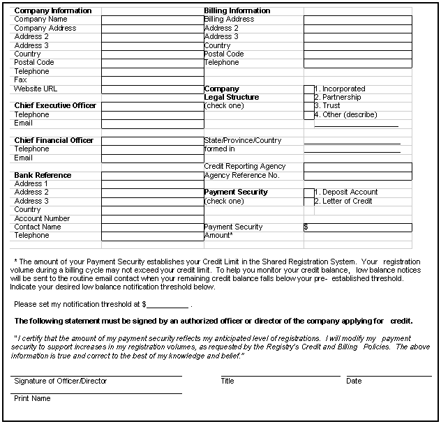
Where a registrar balance is positive, the registrar's registration fees are being reduced from its account. In order to establish an account, a registrar must fill in a Credit Information Form and a registrar Data Form.
Registrar Data Form
2. Account and Billing Payment Policies Registrars must have a registrar Credit Information Form and a registrar Data Form on file with the registry. Charges for domain name registrations will be handled similar to a credit card. The registrar's credit limit is based on the irrevocable letter of credit, cash deposit, or combination thereof maintained with the registry. As domain names are registered, the registrar account is reduced. A monthly invoice will be mailed from the registry to the registrar for domain names processed during the preceding month. The registrar must pay this invoice upon receipt in order to ensure timely processing of future domain name registrations. If the registrar should fail to pay the invoice within terms or if the payment security should be depleted, registration of domain names for the registrar will be suspended and new registrations will not be accepted until the payment security is replenished. Therefore, the registrar should ensure timely payment of invoices and should provide the registry with a notification threshold sufficient to prevent the payment security account from depleting to zero. The registry will permit two forms of payment security: cash deposit or letter of credit.
3. Letter Of Credit Requirements The requirements for a registrar to provide a letter of credit is provided in Appendix C. The billing subsystem handles all billing events from the registry that are created as part of normal registry operations. This mechanism also handles requests from the registry Administration facility. The billing mechanism interfaces with the registry financial system by way of a database interface. The billing subsystem is composed of the following:
The "XRS Billing" subsystem executes as a part of the same subsystem that controls base registry transactions. This ensures transactional integrity between the billing server and the registry server. Examples for billing events handled by the API are:
The registry sends billing events, which require an immediate response enabling the registration process to take place. The billing implementation reflects a pre-paid billing model where a balance is debited for each bill event presented. A negative response is returned by the billing subsystem if there are not sufficient funds available to complete the requested event. An EPP operation that receives a negative response from the billing subsystem will return an "operation failed" response to the registrar that initiated the operation. Each Billing subsystem event has a dependency on the registry Administrator having done the following:
Billing events will record the "Transaction ID" as outlined in the EPP specification. This enables registry events to be traced in terms of their billing consequences. Moreover, reversed billing events will record the transaction ID of the reversing event, and the original, charged event, in order to allow a complete audit of reversed events. 5. Using the Web Admin Interface a. Registrar Accessing On Line Account Information Registrars can access their account information through the SSL-secured registry administrative interface. The following procedures will provide registrars access to their account information:
The same interface can be used to change the registrar contact information. These contacts must exist already within the registry database. The contacts represent the people to be contacted by the registry for various administrative, billing, and technical functions. Registry administration will be performed via the same Web admin interface that registrars may use to update their contact information and query their balances. Administrator staff will be able to perform any operation on any registrar's account. There are several registry-only functions. These include:
Permission to perform the various functions available through the interface
is granted according to the roles system, an access-control list function
implemented in the billing subsystem. Only registry administrators have
access to all functions, including the ability to use the interface to
manage accounts for administration staff and define roles to restrict
the functionality available to an account. Because registrars may have different staff members to control the operation of their registrar software and the financial arrangements they make with registries, PIR will provide registrars' billing contacts with e-mailed notification of a low balance. This notification will result from the registrar reaching a pre-determined threshold. The threshold is calculated according to a preset formula: A notification message might look like this:
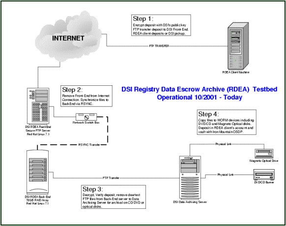
The registry software is designed and the servers are selected in such a way that a complete failure should never happen. In order to offer additional insurance, however, and in order to provide a comprehensive backup strategy in the unlikely event of a registry failure, the registry has a comprehensive backup strategy in place to ensure continued operations. PIR will maintain geographically separated live instances of the database, in order to reduce the risk of needing to restore anything from backups. These instances will be connected by redundant virtual private network connections, to ensure that the stand-by site is always synchronized with the primary site. In the event of a catastrophe in the first location, the second location will allow the registry to continue to function with a minimum of disruption. The secondary location will mirror the primary using a redundant Virtual Private Network, to avoid the possibility of data loss. Zero-downtime, snapshot backups will be performed daily, at midnight UTC. No special procedures are required to put the database in backup mode. The backups will be made directly to the redundant-fiber-channel attached RAID array, and then copied (at lower speed) to LTO tapes housed in a local tape library. Tapes will be rotated in and out of the library in such a way as to maintain a long-term archive. One backup per week will be sent off-site and stored until locally-housed backups expire. Additionally, one backup per month will be stored off-site indefinitely, in a Class A secure location. (Please see section C17.9 for additional details on security.) Other backups are overwritten after 30 days. The backup device and media offer high reliability. PIR will select only LTO drives using error-correction protocols during read and write operations, to ensure that no random errors are introduced to the data during transfer to tape. Mean time between failure for LTO drives is approximately 250,000 hours at 100% duty cycle, with a head life of approximately 60,000 hours. The database backup will also be deposited each day with DSI Technology
Escrow Services, a division of Iron Mountain Incorporated (NYSE: IRM).
Iron Mountain/DSI is the leading software and data escrow company in the
world, with more than US$1 billion in yearly revenues. The files will
be encrypted using OpenPGP as documented in RFC 2440 [http://www.ietf.ORG/rfc/rfc2440.txt]),
and sent to the secure servers of the escrow agent. Iron Mountain uses
an internally secure method to ensure the integrity of all deposits. Servers other than the database will be backed up daily, and seven versions will be maintained of all active files. One backup per week will go to the off-site facility, and recycled when the local copies expire. If a file were to be deleted, all versions would be stored for 60 days; the newest version would be kept for a total of 90 days. The new registry's design offers a better, easily audited escrow facility than the current .ORG registry. Once all registrars have moved to EPP, and .ORG has become a full thick registry, there will be a single, authoritative source for data on registrants for each domain. The single data source means that only one escrow deposit needs to be audited to check for compliance.
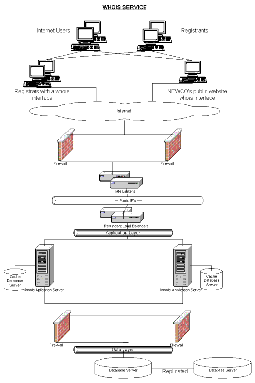
WHOIS (Port 43) PIR will maintain a registry-level centralized WHOIS database that will contain information for every registered .ORG domain. The WHOIS service will be available on the common WHOIS port (Port 43). The WHOIS service will contain data submitted by registrars during the registration process. Any changes made to the data by a registrant will be submitted to the registry by the registrar and will be reflected in the WHOIS in near real-time, thus providing all interested parties with up-to-date information for every .ORG domain. This WHOIS maintained by PIR will be authoritative, consistent and accurate, as people do not have to query different registrars for WHOIS information, as there is only one central WHOIS system. WHOIS will be used to look up records in the registry database. Information about domain, host, contact and registrar objects can be searched using this WHOIS service. The "thick" registry model will be designed based on the EPP protocol. More details on the implementation of the EPP model can be found in Section III, C17.2. The registry WHOIS system will be designed keeping in mind robustness, availability and performance. Additionally, provisions for detection of abusive usage (e.g. excessive numbers of queries from one source) will be made. The WHOIS system is intended as a publicly available single object lookup. PIR will use an advanced, persistent caching system that ensures extremely fast query response times. The information available through the registry WHOIS database will include:
PIR will provide an input form from its public Web site, through which
a visitor can perform WHOIS queries. The input form will accept the string
to query, along with the necessary input elements to select the object
type and interpretation controls. This input form will send its data to
a server, whose function is to perform a port 43 WHOIS query as described
above. The results from the WHOIS query are returned by the server and
displayed in the visitor's Web browser. Please refer to Section V for details regarding the Extensible WHOIS service. For all WHOIS queries, the user must enter the character string representing the information for which they want to search. Use the object type and interpretation control parameters to limit the search. If object type or interpretation control parameters are not specified, WHOIS searches for the character string in the Name field of the Domain object. WHOIS queries can be either an "exact search" or a "partial search", both of which are insensitive to the case of the input string. An exact search specifies the full string to search for in the database field. An exact match between the input string and the field value is required. For example, 'icann.org' will only match with 'icann.org." A partial search specifies the start of the string to search for in the database field. Every record with a search field that starts with the input string will be considered a match. For example: icann.org' will match with 'icann.org' as well as 'icann.org, Ltd.' By default, if multiple matches are found for a query, then a summary containing up to 50 matching results is presented. A second query is required to retrieve the specific details of one of the matching records. If only a single match is found, then full details will be provided. Full detail consists of the data in the matching object as well as the data in any associated objects. For example: a query that results in a domain object will include the data from the associated host and contact objects. WHOIS query controls fall into two categories: those that specify the type of field and those that modify the interpretation of the input or determine the type of output to provide. Object Type Control The following keywords restrict a search to a specific object type:
By default, if no object type control is specified, then the Name field
of the Domain object is searched. The following keywords modify the interpretation of the input or determine the level of output to provide:
By default, if no interpretation control keywords are used, the output will include full details if a single record is found and a summary if multiple matches are found. This section describes the output fields provided for each type of object. A WHOIS query that results in domain information will return the following fields from the Domain object and the associated data from Host and Contact objects. This set of data is also referred to as the Domain Record.
A WHOIS query that results in name server information will return the following. This set of information is referred to as the Name Server Record or Host Record.
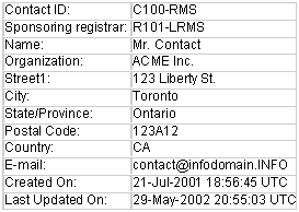
A WHOIS query that results in contact information will return the following. This set of information is referred to as the Contact Record.
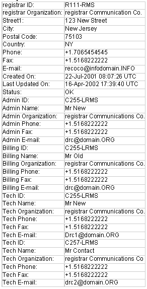
A WHOIS query that results in registrar information will return the following. This set of information is referred to as the registrar Record.
Input: Output: Input: Output: Input: Output: Input: Output: There will be two (2) WHOIS Servers (Load Balanced) on two physical Enterprise Sun Servers for N+1 Redundancy. These will be on a Shared Application server with an instance of Web Server and registry Server running on each Enterprise Server. For details on Hardware architecture please refer to Section III, C17.1.
In order to ensure the integrity of the registry, the registry will adopt a many-layered security approach. The registry designs its security policies and procedures according to the principles expressed in RFC 2196 ([http://www.ietf.ORG/rfc/rfc2196.txt]). Ensuring security is naturally related to ensuring reliability. Items C17.13 and C17.14 of Section III consider the system from the point of view of reliability. This complete computer security plan addresses policy, physical security, and electronic security. It also includes plans for the eventuality of a security breach. Our comprehensive plan covers all those areas. Any security plan requires complete policies which specify who is responsible for each component of the plan, what steps are to be taken to ensure compliance with the plan, and what procedures are to be followed in the event of a failure. registry operations will be charged with following Internet best practices in configuring and monitoring all servers and services. An effective and comprehensive set of authentication policies will specify and ensure appropriate trust relationships. Policies will be specified for both electronic and physical authentication, and comprise authentication of registrar hosts, as well as authentication of staff working locally and remotely. Electronic authentication policies will also specify handling of passwords and the expiration of certificates. A clear accountability policy will define what behaviors are acceptable and unacceptable on the part of non-staff users, staff users, and management. A documentation policy will set out how documents are to be handled, where they are to be stored, and who may access them. A violations policy will specify what reports must be made, and to whom, in case of a violation. Periodic audits of policies and procedures will ensure that any weakness is discovered and addressed. Aggressive escalation procedures will ensure that decision makers are involved at early stages of any event. The registry will locate its servers in high-security, geographically separated data centers. These centers are staffed by security officers 24 hours a day, 365 days a year, and are monitored by security cameras. Access to the facility itself is controlled; those arriving must sign in, and present evidence of identification. Once inside the center, a person is subject to increasingly stringent access controls, including various types of token-based and biometric identification. Visitors are never allowed into the locked cages where the machines reside, and are escorted at all times. Access logs are audited quarterly to ensure compliance. The geographic dispersal is intended as a measure to ensure that, in the event of the total destruction of the primary data center, registry operations may continue without interruption, and to ensure that an attack or catastrophe in one center will not automatically affect all data stores. The data centers are supplied with multiple redundant uninterruptible power supplies, to ensure consistent and reliable power. They are equipped with redundant diesel generators, in order to tolerate extended power failures. They are telco-grade facilities, with multiple redundant connections to the Internet, and have fully-redundant climate-control systems to provide the correct operational conditions for all servers. PIR registry operations staff will be located in Toronto, Ontario, Canada. The offices are located in a building with security guards posted 24 hours a day, 365 days a year. Access to servers and network equipment is limited to systems staff. Electronic security requires correct systems design, to ensure that services are offered with a minimal exposure; correct authentication design, to ensure that only the right agents connect to the offered services; and correct defensive design, to ensure that malicious or mistaken uses cannot cause difficulty with the offered services. The SRS, its associated support infrastructure, and name service operations require distinct approaches to security; these are outlined below. The registry designs use a five-tier design to ensure that each service is exposed only as much as is necessary. Different services are isolated in order to reduce exposure. The tiers are segmented on the network.
The registry will use only strong encryption and multiple authentication methods in any tier except the Web server tier. EPP connections will be encrypted using SSL, and authenticated using both certificate checks and login/password combinations. Web connections will be encrypted using SSL in the browser, and authenticated in the same manner as EPP connections. Connections to the extranet are limited to pre-approved IP addresses, so that an attack would have to come from a trusted source before it could attempt to foil other authentication methods. A practical effect of having to communicate with registrars to provide, for instance, technical support means that some communication will have to be done outside the SRS. To prevent this out-of-band communication from becoming a weakness in the security, PIR will use a system of passwords to authenticate the originator of every technical support enquiry. Finally, in order to ensure that malicious or mis-configured hosts cannot deny service to all registrars, the .ORG registry will use traffic-shaping and quality of service technologies in order to prevent attacks from any single registry account, IP address, or subnet. This additional layer of security will reduce the likelihood of outages for all registrars, even in the case of security compromise at a subset of registrars. The system will be monitored for security breaches from within the data center, using both system-based and network-based testing tools developed by IBM (see figures). Operations staff will also monitor systems for security-related performance anomalies. Triple-redundant monitoring ensures multiple detection paths for any compromise.
Backups will be sent to an off-site, secure storage facility. Escrow deposits will be encrypted using OpenPGP, and deposited in a secure facility. (For additional information about backups, see Section III, C17.7.) The layered design, combined with strong encryption and multiple authentication ensures the security needed to the system, while ensuring that needed services are always available. Support infrastructure System management will for the most part occur remotely, via high-speed virtual private network connections. IPsec and ssh will be used in tandem, in order to provide spoof-resistant, secured connections in all cases. In order to ensure that the management interfaces do not become a "back door" to the system, strict controls are placed on who may connect to the VPN, and from what hosts. Connections are authenticated within the virtual private network (which includes machines in the operations center, as well as a small number of remote machines) using an IPsec-based public key infrastructure.
The operations network is segmented, to limit access through it to the SRS management network: several layers of password and certificate authentication are necessary to connect to the management network. Please see Section III, C17.5 for details on the security of the DNS system.
1. Sustained and Peak Bandwidth While projected sustained bandwidth for the .ORG registry is currently 3 megabits per second, the Internet connectivity solutions provided for at both the primary and secondary sites are dynamically scalable to 100 megabits per second. 2. Registrar Add Storms, Rate Limiting and Guaranteed Bandwidth a. Bandwidth and Connection Throttling Controls In the event of unexpected or unplanned load that results in contention; the registry server complex has the ability to provide equal access to all registrars for those available resources through use of a rate-limiting and bandwidth shaping network appliance (please see Section III, C17.1). This device will limit each registrar from their permitted known IP sources to a combined maximum number of concurrent connections to the registry. The total number of connections permitted to each registrar will be decided based on connection usage policy to be stated in the final registry/registrar agreement. These devices are also capable of throttling or shaping specific types of packet requests, allowing the registry operator to set priorities on not only the number of concurrent connections a registrar is permitted, but to also prioritize the type of traffic. These devices are part of a strategic design to handle aggression attempts to register desirable names pending re-release. Fair access to public WHOIS services will be handled using a combination of total concurrent connection handles, limitations to wildcard searches, and an aggressive high duplicate response system (specifically designed to handle large volumes of repeated same requests). Please refer to Section III, C 17.8. b. Definition of Server Capacity When referring to server capacity or usage, capacity will refer to a combined metric of CPU, and memory in regards to application and database servers. i. Application Layer The registry applications are designed to have stateless operation with load balancers (See Hardware Architecture). This permits dynamic scaling at the application layer for all registry functions. The registry applications are expected to exercise 5-6% sustained load on the currently slated application servers, with bursted loads of up to 12-13%. The registry application servers will be operated with a minimum bursted capacity of 50% over sustained loads. In the event of unexpected load increase, this available overhead should permit the registry Operator to promote additional application servers into production without expected degradation of service. ii. Database Layer Database servers in use will have the capacity to dynamically add additional processors and memory. As primary services will be balanced across the two main database load averages on currently slated database servers are expected to operate at a sustained 12-15% of capacity, with bursted loads of 20-25%. The database servers will be operated with a minimum bursted capacity of 50% over sustained loads. (Multi-version concurrency control (MVCC) ensures that every user sees a view of the database proper to the transaction. Traditional locking makes for slow query times when under high load. MVCC prevents that problem, meaning that queries are just as fast for 1,000 users as for 100 or 10-see diagram below). In the event of unexpected load increase, this available overhead should permit the registry Operator to add additional memory and CPU to continue to scale load appropriately. Disk storage space is provided for in an external disk array and can be added to dynamically, available unused disk space will be maintained at levels of 50% over sustained usage. In addition, the registry operator will continually monitor new advances in dynamically scalable database clustering technologies, with the intent of incorporating such a solution when proven reliable and secure. In view of the current design of the registry database, which focuses on two main databases, this data structure can be further distributed across more databases in the event of unexpected increased load.
iii. Backup Systems Backup Systems are based on high-speed, production to cached disk to high capacity LTO drives in both the Primary and Secondary Sites using Tivoli Storage Manager. This is a fully managed service provided by IBM and is dynamically scalable (on demand) to be able to provide multi terabyte storage capacity if required (Please refer to Section III, C17.7). iv. Escrow Systems Iron Mountain receives escrowed data on a daily basis through encrypted transmission across the Internet. (Please refer to Section III, C17.7 for more). Iron Mountain provides dynamically scalable multi-terabyte storage as required. v. Maintenance Ongoing maintenance work is largely focused on live vacuums and optimization of the databases. Although larger than expected loads may require increased frequency of vacuums, increased vacuums are not expected to require additional resources. Other uses of maintenance periods include the updating of registry software to add enhanced and improved feature sets. Additional and unexpected loads will not affect the maintenance periods required for code promotion except in the event of a large schema change. Although the current design of the registry database focuses on two main databases, this data structure can be further distributed across more databases in the event of unexpected increased load. This would allow a phased approach to database maintenance cycles and schema changes with code promotion, allowing the registry to maintain the slated maintenance cycles. In the event of unexpected volumes of registration, the primary staff area that would be affected would be technical and customer support staff. These departments are structured heavily with well-documented procedures and training materials - permitting a rapid ability to train additional staff. Running on a 24/7 basis, the technical support group currently has the ability to double up personnel on a shift-to-shift basis in response to unexpected load capacity. In further support of these areas, there are at any given time two managers available on call to assist with any unexpected staffing issues.
Afilias' Technical Support and Customer Service departments are recognized as among the best in the industry. PIR intends to provide the same personalized service to all.ORG registrars, registrants and other constituencies, including governments, attorneys and others. Afilias currently employs eight (8) full-time staff to provide 24/7 coverage of all customer service and technical support issues. The staff are highly skilled, and has more than 30 years of combined experience in technical support and customer service. The registry's customer service will be organized into the following departments.
1. Front-line Customer Support The front-line support is the first point of contact for .ORG registrars. This 24/7/365 operation will be able to answer general registrar questions. If the query is out of the bounds of customer support, a service support case is opened and a support ticket is issued. These support tickets are escalated to either the technical support team or the administrative/financial/billing support team depending on the nature of the problem. Methods of contact that will be supported by customer support will include: telephone, fax, postal mail and e-mail. Web-based self-help shall be made available to the registrars that will include:
2. Administrative/Financial/Billing Support The administrative/financial/billing support team will deal with registrars' business, account management, financial and billing issues. Examples that fall into these categories include:
The support team will have guidelines to ensure a conduit exists for escalation to higher levels of the registry's management team with respect to unresolved administrative/billing/financial issues. The technical support team is responsible for dealing with registrars' technical issues. Technical support will be provided through our central Help Desk. Access to the help desk telephone support is through an automatic call distributor that routes each call to the next available Technical Support Specialist. The Technical Support Specialist will authenticate the caller by using a pre-established security pass phrase. Request for assistance may also come to the technical support via e-mail, fax or Front-line Customer Support. The registry shall provide a complete package of support services through the Technical Support Group (TSG). These services shall be dedicated primarily to authorized registrars, although inquiries from potential registrars or those in evaluation stages shall also be supported. Overall, the TSG will provide around the clock, real time professional support ranging from basic inquiries to high-level operations critical technical support. The registry's operation staff shall be available 24/7/365, with required members of the department on call. Escalation procedures shall be in place ensuring that management is notified of service outages in a timely manner. 4. Ticketing System and Call Statistics The registry's Help Desk uses an automated software package to collect call statistics and record service requests and trouble tickets in a help desk database. The help desk database documents the status of requests and tickets, and notifies the help desk when an SLA threshold is close to being breached. Each customer and technical support specialist uses our problem management process to respond to trouble tickets with a troubleshooting, diagnosis, and resolution procedure and root cause-analysis. The TSG shall have access to registry data sufficient to support authorized registrars, to the extent that current operating status can be determined, response to specific registrar queries about registrar specific data or specific transactions can be provided. PIR employees shall be required to properly identify the authorized registrar before providing any registrar critical data, and shall be prohibited from providing information about other authorized registrar operations. The registry's TSG shall be responsible for notifying Authorized registrars of upcoming maintenance and outages with strict requirements regarding advance notice. At a minimum, all planned outages and maintenance shall be announced at least 7 days prior to the scheduled date. Further, the TSG shall be required to provide immediate notice of unplanned or unscheduled outages and maintenance. 7. Customer Escalation Process The TSG will operate with an escalation device. Normally support calls or other forms of communication shall start with the lowest level of support, and be escalated should the first level of support be insufficient. In cases where higher levels of support are immediately apparent (all levels of support staff will be trained in identifying these) the escalation chain may be jumped. Also, should the time limit expire with no notice, the support level may be escalated. The escalation levels and response requirements are as follows: Technical question, usually unique to the registrar that may require support from a registry systems operator or engineer. Responses to requests for information or technical support shall be provided within one hour unless is it deemed to be a Level 2 incident. Systems outage involving non-critical operations to the registry affecting one or more registrars only, but not the entire system. Response reports shall be provided every 30 minutes, by no less than a qualified registry systems engineer. Catastrophic outage, or disaster recovery involving critical operations to the registry overall. Response reports shall be provided every 15 minutes, by no less than a senior registry systems engineer. 8. Security of Customer Support Service Since the registry customer service will also be able to take actions on behalf of registrars, the personal communication process must be secure as well. Registrars will have to supply a list of specific individuals (5 to 10 people) that are authorized to contact the registry. Each individual will be assigned a pass phrase. Any phone requests made by a registrar to registry customer service will have to come from one of the authorized contacts, and require the pass phrase to be supplied. In the event that an attempt is made to contact the registry support on behalf of a registrar, but appropriate authentication is not provided, the registry will make contact with the registrar to inform it of a breach of security protocol. 9. Registrar Contact Information The registry's TSG shall maintain a registrar contact information database in order to ensure it has an accurate list of appropriate registrar contacts and pass codes. 10. Customer Satisfaction Surveys In order to fairly judge the quality of its customer services and to ensure that the .ORG registry provides around the clock professional support to its customers, PIR will perform customer satisfaction surveys on a regular basis. The result of these surveys will be used to identify and correct problems with the customer service process. The registry will also use these results to measure improvements in customer satisfaction. Afilias' Customer Service, Support, and Technical staff are all experienced in handling the wide variety of issues that a registry will encounter. The .ORG registry will have superior customer service, with a very fast response time, as a result of our experience and skills.
The graph above shows the monthly call and e-mail volumes handled by the Afilias .INFO registry Customer and Technical Support department from May 2001 through May 2002. Four periods are highlighted in the graph:
At present the .INFO registry supports more than 100 .INFO-accredited registrars from about 20 different countries, along with providing support to potential registrars and registrars in the Operational Test & Evaluation (OT&E) phase. The customer service department answers most of the registrant queries.
RFC: RFC954 NICNAME/WHOIS Please refer to Section III, C17.8 for a complete description of the proposed publicly accessible look-up/WHOIS service. RFC954-Conformant WHOIS The standard WHOIS service is intended as a lookup service for registries, registrars, registrants, as well as for other individuals, organizations and businesses that wish to query details of domain names or nameservers stored in the registry. Being a thick-registry, the standard WHOIS service will provide a central location for all authoritative .ORG TLD data. Registrars will be able to provide a front-end Web interface to the standard WHOIS service. In addition, the registry provides its own front-end Web interface to allow convenient user access to the WHOIS service. The RFC954-conformant WHOIS service will be engineered to handle high transaction load and be integral to the standard suite of registry services. The service will return a single response per domain name or nameserver query. The RFC954-conformant service provided by the registry will have the following features:
DNS queries will be serviced entirely through an out-sourced DNS provider. The DNS provider, UltraDNS, hosts the DNS information in its' own proprietary database while maintaining full compliance with international standards for providing DNS information to the Internet community. UltraDNS provides its' services in such a manner as to provide DNS that is both highly available, and high performance. A more verbose description of UltraDNSs facilities and methods is included in section (Section III, C17.5) UltraDNS is based on a non-BIND proprietary code built from the ground up. In addition to supporting the standard DNS specification, there are numerous features and enhancements that have been incorporated into the UltraDNS system, such as server specific responses. UltraDNS has incorporated BGP announcement generating code directly into UltraDNS DNS resovler. This will cause BGP announcements to be withdrawn upon software, server, or network failure conditions associated with the resolver. The code is fully compliant with the following RFCs: 2453, 2080,2328, 2460, 2373, 2463, 2464, 2236, 1812, 1771. UltraDNS BGP routing mechanism, combined with an advanced database schema allows individual UltraDNS servers to return different answers depending on which server actually receives the inbound query. The server can also generate time specific answers, allowing specific DNS records to be excluded from answers during certain periods of time, such as when the target machine is down for a scheduled backup or maintenance. In addition to enhancements to the DNS query/resolution mechanism, there are many other additional features that have been incorporated into the server design. The server maintains a list of authoritative zones, which is consulted on every DNS lookup, allowing per zone query count statistics to be generated effortlessly. These statistics are periodically written to a table in the Oracle database, and are easily available using standard SQL queries. Please refer to Section III, C17.2 for a complete description of the registry-registrar model and protocol implementation. Please refer to Section III, C17.2 for a complete description of the registry-registrar model and protocol implementation.
PIR will use a distributed architecture to achieve the goals of scalability, reliability, and extensibility. Registry facilities/services will be operated in two separate geographic locations, allowing for redundancy and fault tolerance. System redundancies exist at the hardware, database, and application layer. The registry will use load balancers to assist in scalability as well as to prevent service outages. The application layer architecture allows a fully scalable number of application instances of the system to be running simultaneously. Automatic fail-over of the system and subsystems is an integral part of the design of the architecture. The registry will operate several database servers to provide redundancy. The primary registry facility will house two database servers, one being the main database and the other being the secondary database. The standby registry facility will house one database server, which will be constantly synchronized with the primary registry. Connectivity between the Internet and the Primary and Secondary registry is via multiple redundant connections. A separate network is used for backups. Load balancing is used for balancing all aspects of the registry, including the registry gateway, WHOIS services and DNS API Gateways. There will be 24/7 on-site and remote network and system monitoring to ensure system uptime and performance at all times. For more details on the hardware architecture please refer to Section III, C17.1. The registry has developed a highly effective and flexible software development and quality assurance process. Our software is developed with performance and quality as a top priority while using the latest design concepts and tools available. Once development is complete, our software is thoroughly tested using several proven methods and techniques during a rigorous testing and quality assurance process described below. More than any other service, DNS operations require extremely high availability. ISOC's proposal for .ORG takes that difference seriously. The registry, in partnership with UltraDNS, will provide guarantees that name services for .ORG are available 99.999% of the time on an annual basis. This is a significant improvement over the current guarantees for .ORG. This unprecedented availability is due to UltraDNS's infrastructure of multiple, redundant servers, located throughout the world, as well as UltraDNS's peering arrangements with major network nodes. Because of the multi-path replication their databases use, it would require a simultaneous failure of 90% of the servers in order to cause an outage. Overview The registry has chosen to adopt the RAD methodology in its software development process. We have developed a specific framework that is utilized to develop a new software product. This framework involves several encompassing stages, including consultation/business development, core system design, architecture design, operational evaluation, implementation and operational growth and testing. The first stage of the development process is designed to finalize the business elements of the software product. During specialized meeting sessions system requirements, business process flows, business logic, and system data requirements are developed and evaluated. The result of this stage is a focused plan describing what services the software product will provide and how it will function to provide them. With the plan from the initial stage of development completed, the registry will then begin the technical system design. The system design stage is used to develop technical designs of the system. Each different system object/module is designed using object-oriented design tools, pseudo code, and process outlines. Procedures for storing data, interacting with clients and back end operations are designed and evaluated. The result from this stage is an overall technical design and functional specification. Once the technical system design is ready, the hardware and software architecture is developed to provide a platform for the software product. This stage involves evaluating different hardware systems that would be most effective for the software product. These evaluations are based on hardware capability, support systems, and financial considerations. The software architecture is evaluated in a very similar way, specifically focusing on capability, support systems, and experience from other implementations. The final result from this stage is plan for the support systems of the software product. During this stage, members of the management, operations and development teams involved evaluate all plans, specifications and requirements developed during the first three stages. Evaluation takes place in coordinated sessions where any minor changes can be made. However, if a critical piece of the overall plan needs to be changed, the evaluation team can refer the piece to be re-developed in one of the previous stages. The result from this stage is a final and locked software development plan that serves as a full blueprint for the entire project. In this stage, the software product is developed for the chosen hardware platforms and operating system environment using object-oriented programming languages, database development tools, and fourth-generation languages. Development test beds are built for software testing. The software product is built and tested in increments, and the functionality grows with each build, from alpha to beta to full production. The system hardware and software are installed in the planned data centers for rollout and tested to work with the software product. f. Operational Growth and Testing During this phase, the software product is successively upgraded in planned build and release cycles. Software bug reports are addressed in each build and release. Maintenance releases are developed for serious software problems that cannot wait until a planned upgrade release. Each new release is required to go through the registry's rigorous and extensive multi-level quality assurance process. The registry is using object-oriented analysis and object-oriented design tools for requirements evaluation and detailed software design. We employ object-oriented programming, database development tools, and fourth-generation programming languages for software development. The development process is managed by using a Concurrent Version System. This system gives us the ability to maintain a code depository in a central location where all developers can access it. It prevents code mismatch, duplication and other issues that can be introduced when many people are working on the same project. To facilitate bug tracking, the registry uses a comprehensive tracking system. It tracks all bugs found during the various development and testing stages as well managing bug fix timelines, priorities and responsibilities. The following list gives examples of the tools the .INFO registry has used in the past and would use with .ORG: JAVA, SSLava, Xerces, Struts, VI, Electric XML, JSSE, Overview Once the software product has been developed, it must undergo several unique levels of testing. Each level is specifically designed to not only test different functions of the software, but also to verify each function's interactive ness and ability to work as one unit.
Level one is designed to verify that all operational functions of the software are working as designed. This includes all possible commands, negative cases, billing operations, DNS, WHOIS, Web interface and reporting. Any changes to backend/internal logic and operation are also tested. These tests are conducted on a basic system configuration using one test machine. The software product must go through this test a minimum number of times to verify that consistent results are be obtained. b. Level 2: Distributed Environment Testing Level two is designed to test how the software performs on a distributed environment. This means that each separate component of the software is placed on it's own server to simulate real production and then evaluated to make sure that component interaction performs as expected. The functions that are tested here include all possible commands, negative cases, billing operations, DNS, WHOIS, Web interface and reporting as well as any back end changes. This test is similar to the level one test, however it is based on many different machines and the database contains a large dataset. This test is also performed a minimum number of times to verify that the results are consistent. Level three is designed to evaluate our software on a basis of how well it handles different degrees of load. The registry employs many different types of load tests to verify that our software performs to its performance specifications. The load tests are designed to send load incrementally at the server. They start off at a low level, and slowly progress to a massive load scenario that is actually beyond what the system allows during production. Each load test is a series of mutable and non-mutable transactions. These tests not only demonstrate that the system can handle requests from many different connections, but also that data integrity is maintained while client requests are being served. The registry has developed many different tools to test software functionality. We have specialized test harnesses for which many test cases have been developed to evaluate software product. We test the software on many different levels, from pure XML and protocol compliance to high level reporting and accounting operations. Each tool can be easily operated and quickly adapted to many different types of tests. The following is a list of some of the tools we currently employ in our projects.
Overview To facilitate the quality assurance process, the registry has built an extensive testing platform. Hardware that is located in the testing platform is a scaled down version of the production environment. Hardware is divided into two separate sections. The single server section developed for level 1 testing, and the multi- server section developed for both level 2 and 3 testing. Each server is set-up to specific variables to mirror the production environment as much as possible providing a testing platform as reflective of production as possible.
Database and system administration specialists will be available 24 hours a day, seven days a week, to aid in system support when necessary. Any changes will be documented in a central location, so that there is a well-known location for staff to find the latest news about the system. Problems are tracked in a ticketing system that affords the development of a comprehensive system history. The system has been designed and implemented with an eye to simplicity. "Keep it simple" design reduces the potential for failure due to mis-configuration, and ensures that the system is not so complex that no-one can understand it. Modular design ensures the separation of components, so that interdependencies will not render the whole system inoperative if a single component were to fail. These policies and procedures all rely on the extensive experience Afilias has in operating the .INFO registry. PIR will use commercially reasonable efforts to provide registry services for the .ORG TLD. The performance specifications provide a means to measure registry operator's delivery of registry services including WHOIS and DNS. Please refer to Section V, C28 for details concerning registry performance specifications.
The design of the .ORG registry software relies upon multiple, high-availability components in order to reduce the risk of failure. The SRS and WHOIS services will be able to continue to function, even in the event of a total failure of one server. Subsystems will be interconnected with redundant networks, to ensure that a data path is always available. The whole system is designed to avoid "Single Points of Failure." The registry's design is a tested, stable design, based on the experience of implementing other registries, such as .INFO and .AU. There are five factors that allow PIR to design a reliable system, resistant to outages. First, the registry will select hardware that is tolerant to fault, so that in most cases the hardware can function even if part of the hardware is damaged, and can be serviced without interruption. Second, the registry will build the system with multiple-redundant subsystems, in order to ensure that the entire system remains functional even if whole subsystems fail. Third, the registry will place its data centers at multiple, geographically separated locations, in order to guard against the complete destruction of one data center. Fourth, the registry will use hardware and programming techniques which guard against the introduction of bad data, and which will allow multiple audit paths. Finally, the registry will use development and operations policies and procedures to ensure that the system always functions. 1. Preventing Hardware Failures PIR will use enterprise-class hardware, which is designed to tolerate the failure of its components, and which can be serviced without removing power. The failure of a CPU, memory module, disk drive, or system board will not cause the servers to fail, but will generate warning messages to inform systems administrators that a fault condition occurs. Only ECC memory will be used, to ensure a failing memory module cannot affect system operation or data integrity. In the event the ECC memory detects a fault, it will report the fault to systems administrators. In the case of a fault condition, it will be possible to replace the failing component without removing power from the server. The failing component will be replaced, and the server will continue to handle requests. The .ORG registry's system will use multiple-redundant subsystems in order to ensure that, in the event of a failure of any component, the entire system is not affected. Each server in the primary data center will be paired with another server, so that one server may be removed from service without affecting data processing. If it is necessary to remove a single server from service, its paired member will continue to provide the affected service. All network components and data paths are configured in active-standby, fail-over configurations, so that the failure of a component will not affect data processing. In the event one component fails, its pair will automatically take over. External RAID arrays will also be attached by redundant, fail-over links. The facilities will have redundant, telco-grade connections to the Internet. Each server will be served by fully-redundant uninterruptible power supplies, to provide consistent, reliable power. The facilities will be fitted with redundant diesel generators, to be able to weather an extended power failure. Multiple, redundant climate-control units will ensure provision of the humidity and temperature operating requirements of the servers. The components of the system will be located in Class A secure facilities (for additional discussion of facility security, see Section III, C17.9). The primary site will copy its data to other secure locations, so that the complete destruction of the entire primary data center will not destroy the ability to register and query names. 4. Protecting Against Bad Data Except for administration of the system, interaction with the database will happen only through the EPP server. This allows the assurance of careful data normalization before any data reaches the data store. Keeping data normalization and data integrity checks outside the database ensure that no malicious or mistaken input will get into or persist in the system. All servers, data stores and backup devices will use ECC memory and similar memory-correction technology to protect against the possibility that any failing component might introduce random data errors. Regular audits of backups will ensure that data is safe and available.
5. Policy and Procedure: the Human Factor The registry will adopt policies and procedures to ensure its services are always available. These can be divided into three types: operations policies and procedures, quality assurance processes, and approaches to development. Each component will be monitored for security, performance and stability both from within the data centers, and from a remote site. Three different monitoring systems provide triple-checks for potential problems. This allows the earliest possible warning of trouble, in order to allow ample preparation in case of a detected fault. Technical support staff, monitoring systems 24 hours a day, will be alerted immediately in the event of any hardware or software troubles. Second-level technical staff will be available 24 hours a day, seven days a week, to address immediately any potential failure of a system component. Consistent policies on maintenance script placement, commenting rules, and rigorous schedules for audits and maintenance will ensure that the system does not experience outages. Upgrades and maintenance will be conducted according to well-established policies. Each proposed system change will be documented in advance, and will undergo peer review before being implemented. Proposed changes are also tested fully in the quality-assurance
environment before being moved into the live system (see below).
Answers for this item are combined with Section III, C17.16. Please see C17.16 for explanation.
The registry has designed a system with extremely high fault tolerance. Redundant systems, and hardware which allows parts to be replaced without shutting the hardware down, both contribute to making a system that is extremely reliable. In order to complete its responsible preparations for any contingency, however, the registry has a full plan to deal with failure. The registry's technical support will monitor its services 24 hours a day, 365 days a year. At any time, at least two second-level technical staff will be available by pager, to respond to emergencies. The second-level staff will be intimately familiar with the software, and able quickly to diagnose and correct faults. In the event of a software failure that second-level staff members are unable to solve, system programmers will be contacted to work on the fault. The data centers will keep extra parts for all hardware involved, allowing quick repairs in the event of hardware failure. The supplies will be adequate to allow for multiple concurrent component failures. Additional preparedness will come from 24-hour, 365-day-per-year telephone and on-site support from all software and hardware vendors. If replacement parts stock were to be exhausted, additional parts would be available within four hours of request. Hardware will be selected for the highest degree of serviceability. The registry offers a system which avoids complexity. Simplicity in design is crucial for reducing recovery time, because it makes the system easy for administrators to understand. That reduces the time it takes to identify, isolate, and replace a faulty component. There are two classes of potential outage: expected and unexpected. Expected outages are planned events; they can therefore be controlled, and responses to them fall within the bounds of standard operations procedure. In a normal expected outage, a subsystem which is known to be somehow faulty is simply removed from operation; a secondary (backup) subsystem is activated to replace the faulty subsystem. When the faulty subsystem is fixed, it can be reintroduced to the system to replace the former secondary subsystem. All these activities can be accomplished without interrupting data processing. In the event the entire system is expected to fail, registrars would be notified of the anticipated shut-down of the primary data center, and the activation of the stand-by data center. At the announced time, the primary center would be removed from service, and operations would continue at the secondary center. Given the high fault tolerance of the hardware the registry is using, a complete expected outage is extremely unlikely. More likely is planned withdrawal of a single subsystem. In such a case, the system would be reconfigured not to rely on the failing subsystem. The failing subsystem could then be taken out of service for repair. For most subsystems, the reconfiguration would happen without any interruption of service. In the case of removing the primary database from service, it would be imperative to ensure that no transaction was in process during the switch-over; therefore, there would be a short interruption of data processing. There are four classes of unexpected failure:
The registry's preparedness is demonstrated by the step-by-step contingency plans it has for various kinds of outages. Here are some samples. a. In Case of Application Server Hardware Failure In the event of hardware failure on one of the application servers, the systems should not fail. The second server will take over, and continue handling processing. Systems staff will handle all operations to restore the machine. Here are the steps needed to restore functioning:
b. In Case of Reports of Poor Response In the event of calls to technical support complaining of poor service, it is necessary to determine whether there is a real problem in the data center, or whether the problem may be with routes on the Internet. Complaints from multiple registrars should be taken as an alert that something may be wrong in the data center. Technical support and systems staff will need to work together to resolve the problem.
c. In Case Data is Deleted by Malicious or Misbehaving Code A database administrator will determine when the problem began, using database logs and the internal, three-way logging kept in the database. The administrator will determine the scope of the problem in respect of number of records, potential methods of recovery, and estimated time to recovery for each method. Senior management will decide, on the basis of advice of the database administrator, which method to adopt. Because of the permanent deleted-records list, restoration should be possible relatively quickly. The administrator shall check for name-space conflicts resulting from the deletion of legitimate names. Once these exception cases have been cleared, other restoration should be possible in a bulk operation. Full table maintenance is necessary in such a case. Once the data is restored, the administrator is to perform consistency and sanity checks, then contact technical support, and close the trouble ticket. Transition Plan. This should present a detailed plan for the transition of the Registry Function from the current facilities and services provided by VeriSign, Inc., to the facilities and services you propose. Issues that should be discussed in this detailed plan include: (See items C18.1 through C18.7) The registry contemplates a transition path that will have minimal impact on registrars, and will be transparent to the end user community. ISOC's strong technology background, combined with Afilias' experience and skill set in providing registry services, will help resolve unanticipated problems that may arise during the transition process.
The technical transition from VeriSign to PIR will involve a multi-step procedure, outlined in detail below. PIR will also make plans to transition other registry-related functions currently handled by VeriSign. Relevant issues will include (but are not limited to) customer service, policy, legal, and domain name arbitration. PIR's goal is to provide seamless continuity of service to registrars and registrants in all areas. Technical Transition Step 1: Specify data required for conversion The data required for the transition will be detailed to VeriSign, and will include, but not be limited to, thin-registry WHOIS information currently captured by VeriSign, the gTLD zone file for .ORG, and registrar information relating to the operation of the registry (registrar ID mappings, for example). All data currently maintained by registrars will not need to be loaded into the system. Domain names and associated child entities will be converted real-time, as registrars move to the EPP-based system. (See Section IV, C22 for more details regarding how the database will migrate from a thin to thick registry model). The registry data should be formatted in a tab-delimited text file, with the first row containing appropriate column headers. The gTLD zone file can be sent in the current text format. If these formats are determined to be insufficient, an alternative format can be negotiated between PIR and VeriSign, as long as this negotiation does not prolong the process of receiving the data. This data will be formally requested no more than three days following the awarding of the bid. Step 2: Form Registrar Transition Focus Group (RTFG) PIR will immediately begin selecting and contacting registrars to formulate
the Registrar Transition Focus Group. The mission of this group is: 1)
to provide input from a registrar's perspective on the transition, 2)
to provide a level of testing to ensure that the server software is complete,
and 3) to ensure client software can be successfully transitioned in a
timely basis. The RTFG will consist of at least five registrars (and two
alternates) who can dedicate adequate resources to provide relevant data
to the PIR transition team. No later than 25 days after the request in Step 1 has been issued, PIR will expect to receive, in the loadable form decided upon, the complete set of data to be used, solely for the purposes of testing the transition. It will be requested that VeriSign provide approximate times for the data set retrieval and sending, so that the appropriate time can be allocated during the cutover process. Step 4: Run conversion to test environment Upon arrival of the test data, PIR will immediately begin testing the conversion process, and load this data into a test environment to be accessed by both PIR developers as well as the RTFG. The conversion data will be segmented into two files: one considered a "full" data dump, and the second considered an "incremental." The incremental dump will consist of both changes to records in the full dump, as well as new records not previously existing the full dump. The conversion process will involve first loading the "full" data dump, and then processing the incremental dump after. Collectively, this is referred to as the "conversion process." This step will be completed no later than 21 days after the data has been received. Step 5: Confirm readiness of VeriSign DNS API PIR will utilize VeriSign's name servers for the first 180 days of registry operation. As such, PIR will need to get confirmation of the API that will be used by PIR to send zone file information to the VeriSign gTLD name servers. This step is contingent upon VeriSign having a mechanism on its side of the transfer. PIR would expect to have access to a test API system no later than 45 days after the bid award. Step 6: Begin internal and RTFG testing Once the data has been successfully loaded into the test arena, PIR and the RTFG will be allowed to conduct tests on the data to verify registry operations. PIR's initial testing will be conducted using a standard test suite that has already been built by Afilias for the purposes of verifying registry operations. The initial test suite will include the following areas:
Step 7: Implement changes from Focus Group and Internal Testing During the testing phase, problems that are found within the registry
system will be documented, ticketed into the bug tracking system, and
resolved in a timely basis. As problems are resolved, fixes will be introduced
back into the system using the same Quality Assurance procedure that Afilias
uses in its current production environment. While many problems will be
resolved during the initial testing phase, there may be issues that require
an extensive change. Should it be necessary, PIR will take an additional
30 days beyond the initial testing phase to resolve any major issues. Once it is believed that all fixes are in place from the previous steps, PIR will re-run the data conversion process, and the test suite. Again, the RTFG will be encouraged to also conduct testing on their end to verify the results. It is expected that this will take no more than 7 days. Step 9: Begin Data Migration to production system Once the system operations have been verified, VeriSign will need to
provide another full set of data, identical in format and nature as the
data provided in Step 1. This data will be loaded into the production
system using the conversion program, and data will be checked for accuracy.
No transform commands will be allowed on this data. This full data dump
is expected to occur 30 days before the cutover date. An incremental dump
will then be expected 15 days before the cutover, and the incremental
conversion will occur. Again, this data will then be checked for accuracy. At the time of the cutover, VeriSign will shut down their RRP system. This assures that we have a complete set of data when PIR's registry goes live. VeriSign's WHOIS service, as well as the gTLD name servers, will remain operational throughout the cutover. Step 11: Receive last incremental dump from VeriSign Immediately after the RRP shutdown, VeriSign will be expected to run the last incremental dump of the data, and send this to Afilias as quickly as possible, using the same methodology as described in previous steps. Utilizing incremental dumps will help minimize the downtime required in this process. Step 12: Run last incremental conversion into production system Upon receiving the data, PIR will immediately load the data using the incremental conversion process. The data will then be verified for accuracy and completeness, using the same mechanisms that were utilized in the testing environments. Step 13: Bring up VeriSign nameserver API VeriSign will need to back up the current zone file, and bring up the
mechanism to allow PIR's zone file to be transferred to the VeriSign name
servers. Once this mechanism is running, PIR will initiate a push to the
name servers, and verify that all is running correctly. Once all data and the name server functionality has been verified, PIR will bring up the RPP/EPP system. All operations will be carefully monitored throughout this process, to ensure that all registry operations are functioning correctly. Step 15: Registrars begin EPP migration Registrars will begin the migration from RRP to EPP. Each registrar will be given a commercially feasible timeframe to cutover to the EPP protocol (See Section V, part C22 for more details on this migration). This is expected to take 180 days. Step 15.5: WHOIS Services (thin to thick registry) WHOIS services will be provided in the thin model for all .ORG names operating under RRP, for which the central .ORG WHOIS server will provide referrals to the authoritative WHOIS servers. Part of the RRP to EPP transition in Step 15 will include the authoritative registrar populating full contact information required for thick registry WHOIS services. Thick registry WHOIS services will be provided for each .ORG name that has been migrated to EPP. Step 16: Test UltraDNS API and name server functionality Once the cutover is finished, Afilias will begin testing the transfer procedure to UltraDNS. The testing will be conducted in a similar manner as was done with the VeriSign API. This will take 60 days. Step 17: Run Parallel name servers For a period of 30 days, Afilias will send the zone file data to both VeriSign and UltraDNS name servers. The UltraDNS servers will be checked for accuracy and completeness. Step 18: ICANN to switch name server delegation Once the accuracy has been successfully demonstrated, PIR will petition ICANN to switch the name servers from VeriSign to UltraDNS. This is expected to take 14 days. Step 19: VeriSign to remove Afilias connectivity to their name servers As part of the contingency outlined below, it is expected that VeriSign will keep the connectivity to the nameservers alive until 30 days after the delegation change. This step would complete the transition.
One of PIR's goals during the transition is to minimize the downtime incurred in any portion of the registry services. Because the cutover only involves the shutdown of the RRP service from VeriSign, we expect that there will be no interruption of service for the key end user components of name resolution and WHOIS services. By using the incremental dump methodology described above, PIR will minimize the amount of down time that will occur during the cutover process. This will only impact registrars' ability to transform registry-related information, such as name servers delegated to a particular domain, as the registry data will not be accessible during this time. All data maintained by the registrar, in their own WHOIS databases, will not be affected. The cutover process is expected to last for 48 hours. Once the cutover has been completed, no further interruption of service is expected.
Each step in the transition is outlined below, with each step's risk assessment and contingency plan to follow: The transition from VeriSign to PIR involves a nineteen-step procedure: Step 1: Specify data required for conversion Contingency: In the event that VeriSign cannot supply the data in the format suggested in C18.1, PIR will work with VeriSign to establish a format that will be mutually acceptable. Both companies have the necessary and sufficient technical knowledge to agree to a format in a short time frame. Step 2: Form Registrar Transition Focus Group (RTFG) Contingency: Afilias has already experienced previous success in establishing
registrar groups similar to the RTFG during its LandRush 2 process. PIR
will seek out two alternates in addition to the original five registrars
to participate in the RTFG, in case some registrar has difficulty fulfilling
their obligation to the group. Contingency: PIR will depend on VeriSign to be able to deliver data in a timely fashion to Afilias for the purposes of load testing the conversion process. If, however, VeriSign cannot deliver this data in time for the initial testing to commence, Afilias will generate a set of test data from it's current .info production database, with the TLD changed to .ORG, and including only data relevant to the thin registry model. This data should prove to be an accurate model, as the .info production database is a real set of currently resolvable domain names, and the relevant fields will be functionally equivalent. Step 4: Run conversion to test environment Contingency: If problems are found within the test data, then the Afilias development team will work with VeriSign to correct the problem and have the data set regenerated. The purpose of this step is to check for errors in both the data set and the conversion code, so some errors and their appropriate fixes are expected. The largest risk in this step is the indication of an unexpected amount of errors in the conversion code, which could potentially increase the time needed for this step. If this is the case, time will be deducted from Steps 6 and 7 to bring the transition plan back on time. Step 5: Confirm readiness of VeriSign DNS API Contingency: The major risk in this step is the unknown: at the time of this writing, the mechanisms VeriSign will be providing has not yet been determined, so the work involved in preparing for this step is undetermined. It is assumed that VeriSign will have a working model within the timeframe suggested by this proposal. This step can, if need be, be concluded through the completion of Step 7. Step 6: Begin internal and RTFG testing Contingency: Internal testing will begin as soon as the data set has been loaded successfully. The RTFG testing will be available right after the preliminary internal testing has concluded. The largest risk is finding a large problem within the registry software that requires additional time to fix, but this risk has been mitigated somewhat by the inclusion of Step 7. Step 7: Implement changes from Focus Group and Internal Testing Contingency: This step will only be required in the event outlined above
- where a large number of fixes will need to take place before a final
test is conducted. Contingency: The procedures for loading all data will have been fully tested at this point. If, after fixing any problems incurred in the previous steps, the data fails to load, the conversion process will be altered to correct the problem. The time allotment for this step allows for this iteration to occur. Step 9: Begin Data Migration to production system Contingency: At this point in the transition, the data load will have
been tested numerous times. The risk factors here include a problem with
VeriSign providing the production data, or an unforeseen error in the
conversion code - both of which are unlikely at this point. If however,
such an error occurs, Afilias will work expeditiously with VeriSign to
resolve this issue as quickly as possible. This step can occur anytime
within the month prior to the cutover. Ample time has been allocated for
this step in the event of a problem. Contingency: The only potential risk here is having other registry services affected by the closure of the RRP system at VeriSign. It is assumed that VeriSign has run the production system many times in this scenario. In the extremely unlikely event that either DNS or WHOIS services are affected adversely by the RRP shutdown, the cutover will be delayed until the problem can be resolved. VeriSign will be asked to provide, in writing and in advance of the cutover, a statement verifying that the RRP system can indeed be shutdown in this manner. In the event of a catastrophic failure at this point, the conversion will be aborted, and VerSign can re-open their RRP system. Step 11: Receive last incremental dump from VeriSign Contingency: The major risk in this step is timing. It is currently not known how long it will take VeriSign to retrieve and send the incremental data set to Afilias, as this will be determined in Step 3. The RRP downtime will be extended at this point if this step should take longer than anticipated. In the event of a catastrophic failure at this point, the conversion will be aborted, and VerSign can re-open their RRP system. Step 12: Run last Incremental Conversion into production system Contingency: This step's risk is also timing. It will be well known how long it takes to run an incremental conversion - as many as five incremental conversions will have performed at this point. In the event of a catastrophic failure at this point, the conversion will be aborted, and Versign can re-open their RRP system. Step 13: Bring up VeriSign name server API Contingency: If an unforeseen issue should arise, and the registry is
unable to communicate to VeriSign's name servers, attempts will be made
to correct the issue. Should this prove too monumental a task, the conversion
will be aborted, and VeriSign can re-open their RRP system. Contingency: If the registry system fails to come up, or cannot perform all registry services as expected, attempts will be made to correct the issue. If, however, it is determined that a problem exists that cannot be resolved in a timely manner, the system will be brought down, and VeriSign can re-open their RRP system. This risk is considered "High" because this marks the "point of no return" for the registry. Step 15: Registrars begin EPP migration Contingency: Each registrar will be handled on an individual basis with PIR to migrate their systems over to EPP. The RRP to EPP proxy allows registrars to continue to perform domain functions while they are preparing their systems for the change. In the event that a registrar has problems moving to the EPP system, they can continue to operate using RRP until the proper corrections have been made. Step 16: Test UltraDNS API and name server functionality Contingency: The UltraDNS API is well documented, and the code changes
required to switch to the new name servers should be minimal. This coupled
with the extended time frame allowed make the risk factor low. In the
event that a serious problem should occur, PIR will ask VeriSign to extend
the name server usage for another 180 days - which will utilize the full
12 months provided for by VeriSign. Contingency: This step is done merely as a final test to ensure the name servers at UltraDNS are performing to specifications. There is sufficient time built into this plan to correct any data transfer issues involving the system that were not caught in the previous step. Step 18: ICANN to switch name server delegation Contingency: The largest risk is ensuring the correct name server IP addresses are propagated to the root servers. In the event that the wrong information is distributed to the root servers, ICANN will be immediately contacted to correct the problem as soon as possible. Step 19: VeriSign to remove Afilias connectivity to their name servers Contingency: Once the registry is running on the new name servers, the registry operator will no longer attempt any connectivity whatsoever to the VeriSign name servers. VeriSign can bring down this service at its leisure.
Using this transition model, and assuming all risk factors mentioned above are successfully mitigated using the contingency planning outlined, there will be minimal impact on both end user communities described. The main affect on end users will concern the cutover period, during which registrations will not be accepted into the registry from registrars. This does not, however, preclude registrars from taking registrations in an "offline" fashion, although it will be discouraged by the registry. Once the cutover has been completed, users can expect to see the registry perform according the Service Level Agreements outlined in Section V, C28. PIR's performance guarantee is greatly improved over the current .ORG guarantee, and PIR fully expects this to benefit the end user community. End users will no longer have to travel first to the registry, then to the registrar when searching for a particular WHOIS record, as the registry will become a "one-stop shop" for WHOIS information, much as for .INFO today. Once the registry has switched over to the UltraDNS nameservers, end-users can expect names to resolve in minutes, rather than days. This allows the Internet community to put up Internet services much faster than before. The transition will also benefit the registrar community. By moving to a thick registry model, registrars will no longer need to be responsible for WHOIS services to the end-user community, and can re-deploy their resources as they see fit.
As the current operator of the .ORG registry, VeriSign must play an integral part of the transition process. To successfully transition the registry, PIR will require the following from VeriSign:
Afilias, through its relationship with AusRegistry Pty. Ltd, will be conducting the conversion of over 250,000 .AU domain names from a conventional system to the most current version of the EPP protocol. This transition will occur around July 1 of this year. The transition process involves multiple data sources from different organizations, under the supervision of Afilias and the Australian Domain Authority (AuDA). This transition is one of the first attempted in the Internet community in a live production system.
UltraDNS has been providing Managed DNS Service since 1999. In that time frame, UltraDNS has been host to four ICANN-sanctioned TLDs;
UltraDNS has also hosted many customers with TLD-like requirements, such as RegisterFree, NameEngine, and web.com. Additionally, many of UltraDNS's business customers maintain very extensive zone files, or large numbers of zones that are fully maintained. A few examples of these are Impulse Communications, Levi.com, MSN Hotmail.com, Netplan Internet Solutions Ltd., and Oracle and Mail2world, Inc. All of these customers were seamlessly deployed onto the UltraDNS system without disruption of service. Using UltraDNS's database back-end, migration of large customers into
the UltraDNS system is a streamlined process requiring standard zone file
information or just a table of records and values. UltraDNS's largest
zone file transition to date (RegisterFree in January 2001) contained
more than 711,772 resource records. This transition was equivalent to
roughly 500,000 TLD zone entries, and was completed in under eight hours.
The UltraDNS network has been architected for seamless migration of TLD,
registrar, Web host, and other domain name aggregation points. The UltraDNS
data import systems were created to handle large transactions with variable
data sources (zone files, existing DNS servers (using AXFR queries), database
files, and even simple spreadsheets).
The success of this transition will be measured through several mechanisms. The ability for current registrars to be able to immediately perform all current RRP transactions when the registry is cutover will be polled. This will be measured by contacting several registrars within the first week of operation, commencing minutes after the cutover is complete, to assess their level of operation. A comparison of the name server zone files will be conducted after the first push to the VeriSign name servers. The only significant changes to the zone file should be with changes made after the cutover. This will ensure that all names that previously resolved are still in operation. 3. Registration-to-Resolution Test A set of names will be registered through different registrars by PIR, and the total time until the names resolve in DNS will be measured. This will measure the improvement in the domain name registration process as a whole. The information within the registry for both RRP and EPP domains will be examined (although an EPP name cannot be examined until the first registrar goes live with the EPP process) by looking at randomly selected domain names both before and after the cutover. A randomly selected subset of previously registered domains will be tracked for a period of one year. This data will be used to assess the typical types of transforms that occur during the lifetime of a domain, and how well the thick-registry EPP model accommodates these changes. A less empirical measure of overall success of the transition will be to observe how easy it is for registrars to convert their systems to EPP for .ORG domains. A good measure for this is to examine the total number of registrars running within the EPP environment at 30, 60, and 90 days into the new registry operations. Please describe in detail mechanisms that you propose to implement to ensure compliance with ICANN-developed policies and the requirements of the registry agreement.
PIR's back-end registry services provider, Afilias, is an established registry, with close to a year's experience in ensuring compliance with ICANN-developed policies and the requirements. Afilias currently conforms to the policies and procedures under its .INFO Registry Agreement with ICANN. PIR's agreement with Afilias will call for Afilias to implement without fail all ICANN policies and requirements of the .ORG Registry Agreement. In addition to serving the .INFO TLD, the Afilias registry also provides services to the .VC ccTLD, and as a result is experienced at implementing changing regulations and policies across multiple TLDs. For specific details on conformance to Service Level Agreements, please refer to Section III, C17. Afilias has on staff a full-time Registry Compliance Officer, whose task is to ensure that the registry at all times conforms to the exacting standards set forth in its various contracts, including the Registry Code of Conduct found in its .INFO contract with ICANN. The Compliance Officer's tasks include ensuring that the registry provides equivalent access to registrars, monitors potential Conflicts of Interest, and trains staff to comply with regulations that the registry is bound by, OCI (Organizational Conflict of Interest) training, and Confidentiality training. Afilias has created technology that allows it to create the regular reporting of statistics that are required in its Registry Agreement with ICANN. Among other methods, Afilias uses its Statistics Reporting Tool to collect and analyze statistical data. This tool offers its users the ability to analyze the range of registry-relevant data sets (such as registrations, transfers, etc.), and allows its user to display data for any time period, any registrar or registrars, by country, and so on, in a variety of formats. Afilias will adapt this tool for use by PIR for .ORG. The tool is capable of connecting to any ODBC-compliant back end, and is continually being improved.
The registry's deployment of automated techniques results in speed of compliance. In addition, since the registry's members are involved in many IETF proceedings, technical compliance with required policies and procedures will be implemented quickly. Figure 51
C. Equivalent Access for Registrars Please see Section IV ("Provisions for Equivalent
Access by Accredited Registrars") for complete details. |
||||||||||||||||||||||||||||||||||||||||||||||||||||||||||||||||||||||||||||||||||||||||||||||||||
|
| Table of Contents | Section
1 | Section 2 | Section
3 | Section 4 | Comments concerning this site should be sent to
orginfo@isoc.org.
|
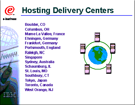
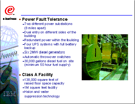
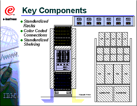
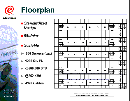
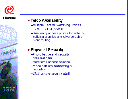
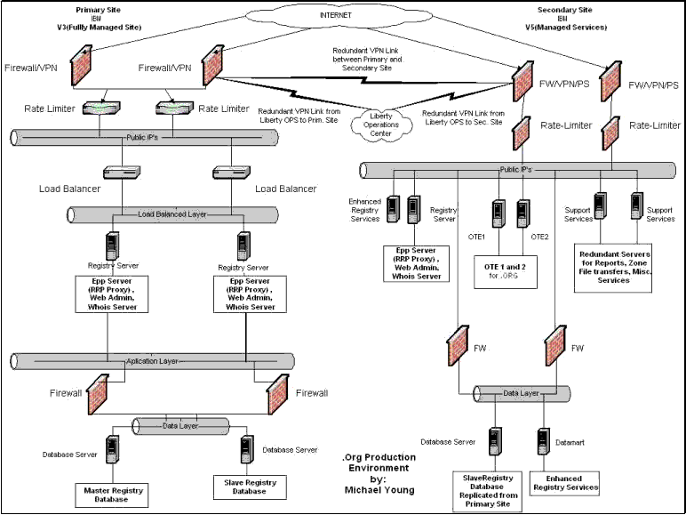
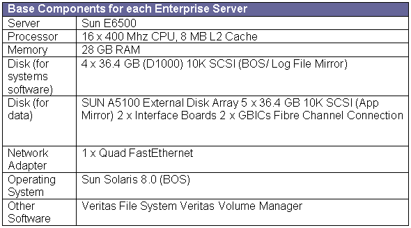
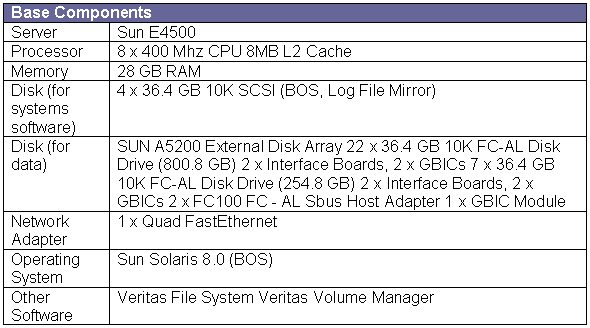
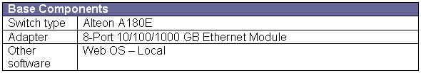
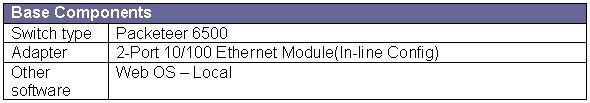
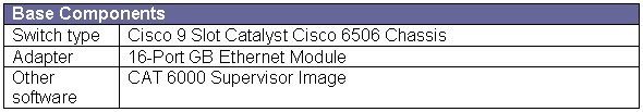

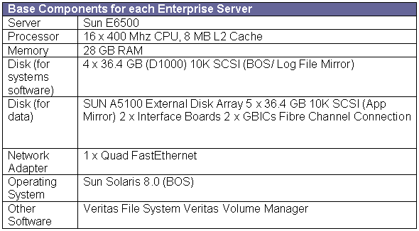


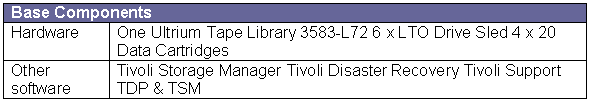
 Connectivity
between the Internet and the Primary and Secondary Registry is via multiple
redundant connections. In addition, connections between servers on the
internal Registry Network are via redundant multi-homed 100 Mbps Ethernet.
Connectivity between the primary and secondary registry facility (for
replication) is via redundant VPN connections.
Connectivity
between the Internet and the Primary and Secondary Registry is via multiple
redundant connections. In addition, connections between servers on the
internal Registry Network are via redundant multi-homed 100 Mbps Ethernet.
Connectivity between the primary and secondary registry facility (for
replication) is via redundant VPN connections.